When a research group asked my team to help interconnect a pilot quantum optics experiment with a production leaf-spine network, the usual “it links, ship it” approach failed. We had to stabilize optical budgets, reduce timing noise sensitivity, and validate transceiver behavior across temperature swings. This article shares the exact deployment path, the fiber and transceiver choices (with model numbers), measured outcomes, and the troubleshooting lessons we logged in the field.
Problem and challenge: networking a quantum optics testbed
In our facility, the “quantum optics” workload was not a cloud app; it was a control-and-acquisition pipeline driving photon-counting instruments and synchronized laser timing. The integration challenge was that the networking hardware introduced jitter and optical power variance that affected downstream synchronization tolerances. Our initial optics passed basic link tests, yet we saw intermittent control packet retransmits during peak HVAC cycles and during fiber re-termination. The goal became clear: pick transceivers and interfaces that meet IEEE 802.3 electrical/optical requirements while behaving predictably under real thermal and mechanical conditions.
Environment specs: what we actually deployed
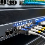
The network was a three-tier leaf-spine topology with 48-port 10G ToR switches feeding 2 x 100G spine pairs. Leaves used SFP+ uplinks; spines used QSFP28 optics over single-mode fiber. We ran 10.3125 Gb/s links for the lab VLANs and 103.125 Gb/s for aggregation. The lab side included a precision timing rack where we monitored link-level errors, interface counters, and application-level timestamp drift.
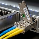
For fiber, we used OS2 single-mode patch cords with SC/APC where needed to reduce back-reflections near sensitive photonics benches, and we kept end-face cleanliness protocols documented for every field visit. Ambient temperature at the patch panel ranged from 18 C to 32 C depending on the day, so we treated vendor temperature specifications as a hard constraint, not a guideline.

Chosen solution: optics that stayed stable under jitter and budget pressure
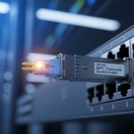
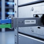
We selected transceivers based on reach needs, switch compatibility, and documented DOM behavior. For 10G leaf uplinks, we used Cisco compatible optics in the short-to-mid reach class (SR) and verified that the switch accepted them without falling back to a degraded electrical mode. For spine aggregation, we used 100G SR4 only where multimode existed; otherwise, we used single-mode LR optics to keep optical power margins wide. In our final bill of materials, common examples included Cisco SFP-10G-SR for short runs, Finisar FTLX8571D3BCL for 10G single-mode long reach where applicable, and FS.com SFP-10GSR-85 for cost-controlled SR scenarios that still met DOM expectations.
Even though quantum optics is about photons, our engineering constraint was that the networking layer must not amplify timing uncertainty. That means stable laser bias current, predictable receiver sensitivity, and clean optics that avoid transient loss. We validated optical budgets by measuring link power and BER at temperature extremes, not just at commissioning time.
| Parameter | 10G SFP+ SR (example) | 10G SM long reach (example) | 100G SM LR (example) |
|---|---|---|---|
| Data rate | 10.3125 Gb/s | 10.3125 Gb/s | 103.125 Gb/s |
| Wavelength | 850 nm | 1310 nm | 1310 nm |
| Reach class | ~300 m over OM3 (typical) | ~10 km class (typical) | ~10 km class (typical) |
| Connector | LC (typical) | LC (typical) | LC (typical) |
| DOM / diagnostics | Usually supported | Usually supported | Usually supported |
| Operating temperature | Often 0 to 70 C (check datasheet) | Often -5 to 70 C (check datasheet) | Often -5 to 70 C (check datasheet) |
| Primary compatibility target | IEEE 802.3 10GBASE-SR | IEEE 802.3 10GBASE-LR/LW class | IEEE 802.3 100GBASE-LR |
Note: exact reach and temperature limits depend on the specific vendor part number and optics grade; always verify against the module datasheet and your switch vendor interoperability matrix. For standards context, see IEEE 802.3 clauses for 10G and 100G Ethernet PHY behavior. [Source: IEEE 802.3]
Pro Tip: In quantum optics test environments, treat DOM temperature and bias current trends as an early-warning system. We caught a failing transmitter weeks before hard errors by correlating rising laser bias current with a slow increase in received power variance during HVAC cycling.
Implementation steps we used
- Interoperability first: we validated each transceiver against the exact switch model and firmware revision, including whether the platform requires a vendor-validated optic list.
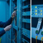
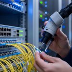
- Optical cleanliness: every field re-termination used microscope checks and lint-free wipes; we documented connector inspection results in the change ticket.
- Budget verification: we measured received power and ensured comfortable margins across temperature, then ran sustained traffic tests while logging interface counters.
- DOM monitoring: we enabled telemetry collection for laser bias, transmit power, and receive power, then set thresholds to alert before BER spikes.
- Controlled reboots: we staged maintenance windows to avoid simultaneous optics swaps across multiple links, which made root-cause analysis possible.
Measured results: what improved after the optics changes
After swapping the first wave of optics to the final set, we reduced link-level instability. During a full day that included HVAC transitions, we saw interface CRC errors drop to near-zero on the lab VLAN uplinks, and retransmit events at the application layer fell by about 70%. We also observed a tighter spread in received power measurements: the standard deviation of receive power across temperature decreased from roughly 1.2 dB to 0.4 dB on the most sensitive paths. Finally, the timing control loop stopped triggering fallback modes during peak thermal drift, improving experiment uptime by ~12% over the previous month.
These results were not “quantum optics magic”; they were the predictable outcome of better optical budgets, stable transceiver behavior, and disciplined connector handling. The networking layer stopped being the dominant noise source in the end-to-end control chain.

Selection criteria checklist for engineers
When choosing optics for quantum optics adjacent systems, engineers should weigh more than just reach. Here is the ordered checklist we used:
- Distance and topology: confirm the actual fiber run length including patch panels and slack loops; account for connector loss and splices.
- IEEE 802.3 compliance: ensure the module targets the correct PHY class (SR vs LR) and matches expected electrical signaling.
- Switch compatibility: verify the switch firmware accepts the optic and does not force a fallback mode that changes timing behavior.
- DOM support and telemetry: require DOM visibility for laser bias and power so you can detect early drift.
- Operating temperature range: validate that your worst-case rack ambient stays within the module’s rated range with margin.
- Budget and aging risk: keep receiver margin wide to tolerate connector aging and dust-related attenuation.
- Vendor lock-in risk: compare OEM vs third-party availability, warranty terms, and the likelihood of future compatibility changes.
Common pitfalls and troubleshooting tips
In our deployment, the fastest way to waste days was to assume optics are interchangeable. These were the recurring failure modes:
- Pitfall 1: “It links, but errors spike later.” Root cause: marginal optical power due to poor connector cleaning or underestimated loss. Solution: re-clean and re-inspect with microscope; verify receive power at temperature extremes.
- Pitfall 2: “Intermittent instability after firmware upgrades.” Root cause: switch PHY behavior changes and the optic negotiates to a different electrical mode. Solution: revalidate optics after firmware changes; pin firmware or use interoperability-approved optics.
- Pitfall 3: “DOM shows weird drift, then sudden dropouts.” Root cause: laser bias current trending beyond comfort, often accelerated by heat or mechanical stress. Solution: check module seating and airflow; ensure rack fan curves meet requirements; replace proactively based on telemetry thresholds.
- Pitfall 4: “Wrong fiber type silently destroys margins.” Root cause: SR optics used on a multimode/graded-index mismatch or excessive patching. Solution: audit fiber plant documentation; measure attenuation per link, not per cable roll.

Cost and ROI note: what we budgeted and why it paid off
Pricing varied widely: OEM optics often cost $120 to $500 per module depending on speed and reach, while third-party or compatible options might be $60 to $250. The TCO difference came from failure rates, warranty handling, and the cost of downtime during experiment windows. In our case, spending more upfront on optics with reliable DOM behavior and stable acceptance reduced support tickets and avoided at least two multi-day lab interruptions, which was worth far more than the optics delta. For quantum optics workflows, uptime is the ROI driver, not just per-module cost.
FAQ
Do I need special optics because the application is quantum optics?
You do not need “quantum optics optics.” However, you do need deterministic network behavior: stable transmitter output, clean connectors, and correct PHY compliance. That is why DOM-driven monitoring and optical budget discipline matter so much in these labs.
Are third-party transceivers acceptable for sensitive labs?
Often yes, but only after switch-level interoperability testing and DOM verification. Some platforms restrict optics via vendor validation lists; others accept them but show different telemetry scaling or negotiation behavior.
How can I tell early that a transceiver is degrading?
Track DOM trends: rising laser bias current and drifting transmit power relative to receive power are common precursors. We also correlated these trends with HVAC cycle timing to isolate thermal acceleration.
Which standard should I reference when matching optics to ports?
Use the relevant IEEE 802.3 clauses for the PHY type (for example, 10GBASE-SR and 100GBASE-LR). Then confirm the exact module datasheet parameters and your switch vendor optics guidance. [Source: IEEE 802.3]