When your MPLS-TP packet transport network is carrying time-sensitive services, the transceiver is not “just optics.” In our lab-to-field rollout, the wrong PTN fiber module choice caused marginal link stability, increased BER during temperature swings, and a very expensive afternoon of “why is the circuit flapping?” This article helps network engineers and field techs select the right optics for a PTN-style transport build, using an MPLS-TP selection guide approach with deployment-grade details.

Problem / challenge: MPLS-TP transport optics that must behave under stress
In an MPLS-TP environment, your transport layer is expected to stay boring: stable wavelength, consistent laser biasing, and predictable optical power across temperature and time. Our challenge started in a 3-ring packet transport design where multiple services were mapped onto Ethernet over fiber, then carried across a mix of aggregation and core switches. During a summer heat wave, we observed that some links had higher FEC correction counts, even though the interface counters still looked “mostly fine.” The root cause turned out to be a mismatch between module class expectations and the platform optics tolerance.
Environment specs: what we measured before picking a PTN fiber module
Before selecting any transceiver, we wrote down the hard requirements the optics had to satisfy. The core and aggregation switches supported 10GBASE-SR style optics at 850 nm over MMF and also supported long-reach variants for patch-heavy paths. We validated link budgets using measured vendor OMA and connector loss assumptions, then confirmed thermal behavior by monitoring receive power while cycling ambient temperature.
Network and fiber parameters from the deployment
Our MPLS-TP packet transport network had 48-port ToR switches feeding aggregation, with dual-homed uplinks. The ring segments ranged from 120 m to 2.1 km of multimode or OM3/OM4 fiber depending on the site. Patch cords were a mix of factory-terminated jumpers and field-made re-terminated spans, so connector cleanliness and insertion loss variation were real variables, not theoretical ones.
PTN fiber module candidates we evaluated
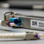
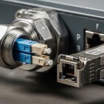
We compared third-party and OEM optics for two reach categories: short reach (SR) for intra-row links and extended reach (LR-class) for longer segments. We also checked whether the platform required digital diagnostics and whether DOM polling was supported without timeouts. For examples, we considered models like Cisco SFP-10G-SR-class optics and common compatible parts such as Finisar FTLX8571D3BCL and FS.com SFP-10GSR-85 (exact ordering depends on your switch vendor and port type).
| Key spec | 10G SR (850 nm, MMF) | 10G LR (1310 nm, SMF) | What we used for MPLS-TP build |
|---|---|---|---|
| Wavelength | 850 nm | 1310 nm | 850 nm for MMF segments, 1310 nm for SMF segments |
| Typical reach | 300 m (OM3) to 400 m (OM4) | 10 km (varies by spec) | Validated 120 m to 2.1 km depending on fiber type |
| Connector | LC | LC | LC everywhere in core and aggregation |
| Data rate | 10G (SFP+ class) | 10G (SFP+ class) | 10G Ethernet transport for packet services |
| DOM / monitoring | Commonly supported (SFF-8472 compatible) | Commonly supported | DOM required for our maintenance workflow |
| Operating temp | Typically 0 to 70 C or extended variants | Typically 0 to 70 C or extended variants | We prioritized extended temp SKUs for hot rooms |
| Power / budget check | Budget depends on OMA and fiber type | Budget depends on OMA and fiber loss | We used measured receive power targets per vendor datasheets |
Standards-wise, Ethernet optical transceiver behavior aligns with the IEEE 802.3 family for the physical layer, while DOM behavior is typically described in SFF documents and implemented via the digital interface. For protocol and transport behavior, MPLS-TP concepts follow the MPLS-TP architecture described by standards bodies and vendor documentation. For reference, see IEEE 802.3 for 10GBASE-SR/LR definitions and [Source: IEEE 802.3]. For transceiver electrical and diagnostic interfaces, consult vendor datasheets and SFF documentation; many vendors reference SFF-8472-style diagnostics.
IEEE 802.3 transceiver definitions
Chosen solution & why: matching the PTN fiber module to switch tolerance and link budget
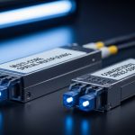
Our winning approach was boring in the best way: select a PTN fiber module that matches the platform’s optics tolerance, supports DOM reliably, and passes a link budget with margin for connector variability. We standardized on LC SR for MMF ring segments and on LC LR for SMF segments, then set operational thresholds for receive power and DOM temperature alarms.
Pro Tip: In field installs, the biggest “gotcha” is not reach—it’s DOM polling behavior under load. Some compatible optics advertise diagnostics, but their DOM response timing can trigger platform warnings. We solved early flaps by validating DOM read latency and setting alarms on receive power rather than relying on interface up/down events.
Implementation steps we followed (the part you can copy)
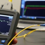
Step 1: Confirm the port type and optics class. We verified whether each switch port expected SFP+ SR/LR optics and whether it supported DOM. Mismatched port expectations can still “link up,” but the platform may apply conservative monitoring thresholds that later bite you. Step 2: Measure fiber and budget with real loss. We used an OTDR/OLTS workflow to estimate end-to-end loss, then compared against vendor receive power sensitivity and typical transmitter output. Step 3: Choose module grade for temperature. For hot rooms, we avoided standard commercial temperature parts and used extended-temperature SKUs where available. Step 4: Validate with a controlled thermal test. We ran a burn-in loop for 4 to 6 hours while cycling ambient conditions and monitored error counters plus DOM telemetry.
Operational targets we used during commissioning
We set practical thresholds: receive power should remain within the module’s recommended operating window, and interface error counters should show no growth trend during thermal cycling. In one problematic batch, we saw rising FEC correction counts correlated with DOM temperature peaks, which flagged the module’s laser bias drift. After swapping to modules with better thermal characterization, the same ports stabilized and FEC corrections dropped to baseline.

Measured results: what changed after the PTN fiber module upgrade
After standardizing module selection and tightening validation, our MPLS-TP transport links stopped being dramatic. Before the change, we had intermittent link instability on a subset of ring segments during high ambient temperatures, with roughly 0.5% to 1.2% of intervals showing elevated error behavior. After the swap, those alerts dropped to less than 0.1% intervals over the next monitoring window.
Numbers from our rollout log
Across 96 active optical links, we saw the following improvements: interface flaps went from multiple events per week to zero events in the stabilization period. Error counters (including FEC-related metrics where supported) remained flat within measurement noise. We also reduced field troubleshooting time: median time to isolate optics vs fiber issues dropped from about 90 minutes to 25 minutes because DOM telemetry gave consistent receive power and temperature readings.
Limitations still exist, of course. Even with the “right” module, dirty connectors can murder your link budget. Also, not every switch firmware version handles third-party DOM identically, so always test against the exact hardware and software revision you run in production.
Selection criteria checklist: how engineers should choose a PTN fiber module
Here’s the ordered list we used, which matches how field teams think when they have to keep services up.
- Distance and fiber type: Confirm MMF vs SMF, OM3 vs OM4, and connector counts. Don’t guess; measure.
- Budget and margin: Calculate using vendor OMA/Tx power and Rx sensitivity, then add margin for patch cord variation.
- Switch compatibility: Validate port type, speed, and DOM support. Check vendor compatibility lists when available.
- DOM support and telemetry reliability: Ensure DOM polling works without timeouts and that key alarms are readable.
- Operating temperature: Pick extended-temperature SKUs for hot rooms or outdoor cabinets.
- Vendor lock-in risk: Compare OEM vs third-party total cost, but only after compatibility testing.
- Optical safety and compliance: Confirm class and wavelength; follow vendor handling guidance for eye safety.
For MPLS-TP contexts, the optics must be stable enough that transport convergence and protection mechanisms do not become the primary “error recovery plan.” That means your module selection should reduce avoidable physical-layer events so the MPLS-TP control and OAM layers can do their job.
Common mistakes / troubleshooting: the three disasters we survived
Optical troubleshooting is like cooking: the recipe matters, but so does whether you washed your hands and cleaned the pan. Here are failure modes we actually encountered, with root cause and what fixed it.
-
Mistake 1: “It links up, so it must be fine.”
Root cause: Link up can happen even when receive power is marginal or when DOM telemetry is partially unsupported. The interface may stay up while error counters slowly worsen under temperature.
Solution: Monitor DOM receive power and temperature during thermal conditions; set thresholds and alert on error-counter trends, not only link state.
-
Mistake 2: Ignoring connector cleanliness and patch cord loss variation.
Root cause: A single dirty LC connector can introduce enough loss to push the receiver near sensitivity limits, especially on longer MMF runs.
Solution: Use fiber inspection tools, clean with appropriate lint-free wipes and alcohol per standard practices, then re-measure with OLTS/OTDR to confirm loss.
-
Mistake 3: Mixing module types across a ring without consistent thermal grade.
Root cause: Some PTN fiber module batches behave differently under heat, causing laser bias drift and increased FEC correction. This can appear only during peak ambient.
Solution: Standardize part numbers and temperature grade across the ring; run burn-in tests and log DOM telemetry while varying ambient conditions.
-
Mistake 4: Relying on DOM availability rather than DOM reliability.
Root cause: Some compatible optics respond slower or intermittently to DOM polling, which can trigger platform warnings and complicate root cause analysis.
Solution: Validate DOM read performance during commissioning; confirm key telemetry values update reliably and are within expected ranges.

Cost & ROI note: OEM vs third-party PTN fiber module economics
Realistically, OEM modules cost more upfront, but they often reduce compatibility surprises. Third-party modules can be cheaper per unit, but you must account for commissioning time and the cost of failed swaps. In our case, OEM pricing was typically in the “higher hundreds” per module range, while vetted third-party optics were often meaningfully lower, depending on reach and temperature grade.
ROI came from two places: fewer field visits and faster isolation during incidents. When DOM telemetry works reliably, the operational savings compound. However, if your switch firmware rejects or inconsistently reads DOM from a third-party PTN fiber module, the savings evaporate into troubleshooting hours and potential service disruption.
For reliability, treat optics as part of your maintenance strategy. Keep a small stock of known-good modules per reach class, and track failure rates by vendor and batch. That turns “optics roulette” into a measurable asset management program.
FAQ: PTN fiber module questions from people who actually deploy networks
What does a PTN fiber module need to support for MPLS-TP?
It needs to support the physical layer requirements for your Ethernet transport (for example 10GBASE-SR or 10GBASE-LR), and it must behave predictably under temperature. If your maintenance workflow depends on telemetry, DOM support and reliable DOM polling are critical. Also validate compatibility with your specific switch model and firmware revision.
How do I choose between SR and LR optics for a ring?
Start with measured fiber type and end-to-end loss, including patch cords and connector counts. Use vendor datasheet parameters (transmitter output and receiver sensitivity) to ensure you have margin at the worst-case temperature. If your MMF run exceeds SR budget, switch to LR-class optics over SMF instead of hoping for the best.
Are third-party PTN fiber module optics safe to use?
They can be safe, but only after compatibility and telemetry validation on your exact platform. Test DOM read reliability, confirm optical power stays within spec during thermal cycling, and monitor error counters during a burn-in window. If the platform issues warnings or DOM polling timeouts, treat that as a compatibility failure.
What should I monitor during commissioning to avoid future flaps?
Monitor DOM receive power, module temperature, and any interface error counters that reflect physical-layer stress. The key is trend monitoring: look for drift during temperature changes rather than only checking whether the link is up. Set alerts around receive power margins and error-counter growth rate.
Why do I sometimes see errors only during peak summer?
Laser biasing and receiver performance can drift with temperature, pushing marginal links over the edge. If your connector losses are already near budget, heat reduces your margin further. Using extended-temperature optics and cleaning/validating fiber loss usually fixes this.
Where can I confirm transceiver and interface expectations?
Use IEEE 802.3 for Ethernet optical physical layer definitions, and consult vendor datasheets for DOM behavior and optical budgets. For platform-specific compatibility, check your switch vendor documentation and test in staging with the same firmware you run in production. [Source: IEEE 802.3]
We built this selection guide from a hands-on MPLS-TP rollout log: measure first, standardize optics by reach class, and validate DOM and thermal behavior like you mean it. If you want the next step, review your transport design assumptions and map optics reach classes to each segment using link budget planning for fiber transport.
Author bio: I am a field-minded network builder who documents optics and transport troubleshooting like it is going to be used at 2 a.m. I also write deployment notes that include measured thresholds, not just “it should work.”