Your network is about to grow faster than your patch panels can politely handle, and the 1.6T fiber module roadmap is the signal. This article helps data center engineers plan for next-gen optical density by connecting module specs to rack cooling, power budgets, fiber plant, and switch compatibility. You will also get a practical checklist, common failure modes, and a cost view that does not rely on wishful thinking.
Where the 1.6T fiber module fits in the optical roadmap
“1.6T” typically refers to a high-capacity optical module class aimed at driving more throughput per slot, often aligned with next waves of parallel optics and tighter electrical/optical co-design. In the field, the real question is less about the marketing number and more about what the module changes in your system: lane count, reach class, optics temperature behavior, and how your switch front-end expects signals. IEEE 802.3 defines Ethernet PHY behaviors (including interfaces for optical links), while vendors publish module electrical and thermal limits in datasheets that matter when you run at high utilization. IEEE 802.3 standards overview
From a roadmap perspective, operators usually move in phases: first, increase port density and keep the same reach; then, increase lane density and reduce per-bit energy; finally, adopt higher aggregate rates per module. The 1.6T fiber module concept pushes you toward more aggressive thermal design and more careful optical budget verification, especially if you are also tightening ribbon routing and panel density.

Key specifications that actually decide success
Before you order anything, compare the optical and electrical realities. Most failures come from assumptions like “all optics are interchangeable” or “DOM is optional.” For roadmap planning, focus on wavelength band, reach target, connector family, transmitter power, receiver sensitivity, and module power draw. Also check operating temperature and any vendor-specific requirements for host support.
| Spec | What to verify | Why it matters in the rack |
|---|---|---|
| Data rate / aggregate | 1.6T-class module interface (vendor-defined) | Drives host PHY lane mapping and switch firmware expectations |
| Wavelength | Common bands: SR-style around 850 nm, LR/ER-style typically 1310/1550 nm depending on product | Determines fiber plant compatibility and attenuation profile |
| Reach | Short reach vs extended reach per datasheet | Impacts optical budget and allowable patch loss |
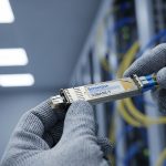
| Connector | LC vs MPO/MTP (often MPO for higher density) | Changes cabling, polarity handling, and panel design |
| DOM support | Digital optical monitoring availability and host compatibility | Enables alarms for bias current, temperature, and optical power drift |
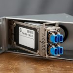
| Module power | W per module at rated conditions | Thermal load and PDU headroom planning; affects inlet temperature margin |
| Temperature range | Commercial vs extended vs industrial (vendor-defined) | Determines whether you can run near hot-aisle limits without derating |
In practice, I have seen “works on the bench” optics fail after installation because the module power and airflow were not modeled for the final rack layout. Even a 5 to 10 C inlet temperature shift can move you toward thermal throttling or elevate bit error rates (BER), especially when the module is packed tightly behind perforated doors. Vendor datasheets usually show power and thermal characteristics—read them like a detective, not like a fortune teller.
Optical budget: the spreadsheet that prevents heartbreak
For each link, validate: transmitter power, receiver sensitivity, fiber attenuation, connector insertion loss, and patch-cord loss. If you are using MPO/MTP trunks, verify polarity constraints and ensure the correct MPO polarity method is applied end-to-end. ANSI/TIA-568 and related cabling guidance help define insertion loss and field test expectations; for optical testing, follow the relevant optical test procedures used by your vendor and cabling standards. ANSI/TIA standards portal

Rack planning impacts: power, cooling, fiber handling, and PDU math
A 1.6T fiber module roadmap is not just optics; it is also power and airflow choreography. Higher aggregate modules often increase per-slot power draw and require tighter thermal management, particularly in high-density leaf or spine switches. Start by mapping module power to your PDU capacity, then compare against your cooling design inlet temperature and allowable delta-T.
Consider a real scenario: a 3-tier leaf-spine topology with 48-port 25G/100G ToR switches is being upgraded to higher density optics on a 42U rack. If you move from lower-power transceivers to a 1.6T-class module family, even a modest increase—say +2 W per module across 96 installed optics—adds +192 W of heat. That is not just an electrical line item; it becomes an airflow requirement. If your cooling design assumes a stable inlet temperature and you are already near the limit, you may need to adjust fan profiles, improve blanking, or revise perforated tile placement.
Pro Tip: When planning for 1.6T fiber module upgrades, test one “full population” link in the target rack at elevated inlet temperature. Benches hide thermal reality; the first thermal soak run often reveals marginal airflow or a host-side lane mapping quirk that only shows up under real thermal conditions.
Selection criteria checklist for a 1.6T fiber module rollout
- Distance and reach class: Confirm the reach spec matches your installed fiber length plus patch and connector loss margin.
- Host switch compatibility: Validate vendor cross-compatibility and firmware requirements; check whether the module needs specific lane mapping.
- DOM and alarms: Ensure DOM works with your platform tooling so you can catch optical power drift early.
- Operating temperature: Match the module temperature range to your measured inlet and hot-aisle conditions; plan derating margin.
- Connector and polarity handling: Decide LC vs MPO/MTP early; standardize polarity methodology and label patch panels.
- Vendor lock-in risk: Compare OEM vs third-party availability, return policies, and whether the host enforces transceiver authentication.
- Cost and power/TCO: Include module power in your PDU and cooling model, plus expected failure rate and spares strategy.
Common mistakes and troubleshooting that saves uptime
Mistake 1: Assuming optics are interchangeable across vendors
Root cause: Host firmware or transceiver authentication requirements differ; lane mapping or electrical characteristics can be subtly incompatible.
Solution: Validate with the exact host model and firmware revision; test with DOM enabled and monitor link stability over time.
Mistake 2: Skipping optical budget math
Root cause: Patch panel loss, connector contamination, and unaccounted fiber attenuation push you beyond receiver sensitivity, increasing BER.
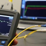
Solution: Do a full budget including worst-case patch cords; clean connectors with validated procedures and re-test with an optical power meter and OTDR where appropriate.
Mistake 3: Ignoring thermal load and airflow constraints
Root cause: Higher module power plus dense packing raises inlet temperature, causing thermal drift or link flaps.
Solution: Measure inlet temperature at the rack and run a stability test during thermal soak; adjust fan directionality, remove obstructions, and improve cable management.
Mistake 4: Mis-handling MPO polarity
Root cause: Incorrect polarity or reversed MPO orientation results in swapped lanes or no light on expected channels.
Solution: Apply the polarity method required by your optics and cabling system; label both ends and verify with continuity testing before connecting.

Cost and ROI note: what to budget beyond the sticker price
Pricing for high-capacity optics varies widely by reach, connector type, and whether you pick OEM or third-party. As a rough planning range, many enterprise transceivers in adjacent high-density classes can land anywhere from $200 to $1,000+ per module depending on rate and reach, while third-party options may be lower but can carry higher variability in DOM behavior and compatibility. In TCO terms, the bigger ROI lever is often power and cooling: if your upgrade increases module power by even a couple watts per optic, the annual energy and cooling load can outweigh the initial per-unit price.
Also budget for spares and testing time. A 1.6T fiber module rollout with tight schedule should include a validation bench, at least one rack-level soak test, and a documented rollback plan to protect uptime.
FAQ
What does a 1.6T fiber module mean in practice?
It usually indicates a high aggregate optical module class designed for more throughput per slot. The exact interface and optics behavior depend on the vendor and the host switch front-end.
Will my existing fiber plant work immediately?
Maybe, but you must match wavelength