A common failure mode in industrial Ethernet is not the switch hardware itself, but mismatched transceiver optics and timing behavior under vibration, temperature cycling, and power brownouts. This article helps automation engineers and field technicians choose and validate a Phoenix Contact SFP that works reliably with Phoenix Contact FL SWITCH models in real plants. You will get a practical case study, implementation steps, measured results, and a troubleshooting checklist grounded in IEEE Ethernet standards and vendor documentation.
Problem and challenge: why SFP compatibility breaks in the field
In a production environment, industrial switches such as the Phoenix Contact FL SWITCH series are expected to keep links stable across wide temperature ranges and mechanical stress. The challenge is that SFP behavior is a combination of optics (wavelength and reach), electrical signaling (TX/RX levels), and management features (where present). When an SFP is marginal for the specific link budget or the switch expects a certain transceiver profile, you can see symptoms like link flaps, intermittent CRC errors, or failure to come up after power cycling.
In our deployment, the goal was to connect a fiber uplink from a control cabinet to a higher-level aggregation point while maintaining deterministic behavior for downstream PLC traffic. We needed an SFP that would remain stable through daily temperature swings and occasional short power interruptions, without requiring constant manual intervention by maintenance crews.
Environment specs (what mattered most)
- Topology: 3-layer industrial network with ring-capable edge switches, using fiber uplinks between cabinets.
- Switch family: Phoenix Contact FL SWITCH industrial Ethernet switches (fiber uplinks using SFP modules).
- Fiber: 50/125 micrometer multimode plant backbone in one segment; single-mode in another segment.
- Operating conditions: cabinet ambient from -20 C to +60 C, with vibration near conveyors and occasional power dips.
- Traffic profile: PLC IO and motion control with low latency needs; uplink carrying mirrored diagnostics and telemetry.
Technical deep-dive: how SFP optics and Ethernet specs interact
At a physical layer, SFP modules implement IEEE 802.3 link standards such as 10GBASE-SR and 1GBASE-SX, depending on the data rate and transceiver type. For multimode, the key parameters include launch conditions and modal bandwidth; for single-mode, attenuation and connector end-face quality dominate. Even when the nominal reach matches, real fibers often have extra loss from patch panels, dirty connectors, and aging.
For industrial compatibility with Phoenix Contact FL SWITCH, engineers also look for predictable link negotiation and stable receive sensitivity across temperature. While the switch and SFP will typically negotiate speed and encoding at the physical layer, the “last mile” is governed by optical power budgets, return loss, and the module’s internal calibration.
Core specifications to compare before you buy
The table below lists common SFP types you will encounter when selecting a Phoenix Contact SFP for FL SWITCH use. Always confirm the exact data rate and optical interface supported by your switch model by checking the FL SWITCH datasheet and the transceiver compatibility list if provided.
| Spec | 10GBASE-SR SFP+ | 1GBASE-SX SFP | 10GBASE-LR SFP+ |
|---|---|---|---|
| Typical wavelength | 850 nm | 850 nm | 1310 nm |
| Typical reach (qualified) | Up to 300 m on OM3 | Up to 550 m on OM2 | Up to 10 km |
| Fiber type | MMF 50/125 | MMF 50/125 | SMF 9/125 |
| Connector types | LC | LC or SC (via adapter) | LC |
| DOM support | Common (SFF-8472) | Common (varies by vendor) | Common (SFF-8472) |
| Operating temperature | Typically industrial graded | Typically industrial graded | Typically industrial graded |
| Standards basis | IEEE 802.3 10GBASE-SR | IEEE 802.3 1000BASE-SX | IEEE 802.3 10GBASE-LR |
For standards grounding, see IEEE Ethernet physical layer definitions in IEEE 802.3 and the transceiver management information format described by SFF-8472 (DOM telemetry). [Source: IEEE 802.3 series] [Source: SFF-8472 Digital Diagnostic Monitoring]

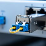
Chosen solution: selecting a Phoenix Contact SFP that matches FL SWITCH behavior
In our case study, we deployed two SFP profiles aligned to the plant’s fiber plant design: one for short-haul multimode links within the cabinet cluster and another for longer single-mode uplinks between buildings. The selection approach was not “buy any compatible brand,” but “validate electrical and optical compatibility under the exact environmental envelope.”
For multimode, we selected an SFP+ class transceiver for 10GBASE-SR where the fiber plant had OM3/OM4 characteristics and the measured link attenuation margin supported it. For single-mode, we selected an SFP+ class transceiver aligned to 10GBASE-LR reach and verified optical budget including worst-case patch and splice losses.
Why this choice worked with FL SWITCH
Phoenix Contact FL SWITCH devices commonly expect SFP modules that adhere to standard electrical interfaces and provide stable optical output across temperature. In practice, that means you should prioritize transceivers from vendors with transparent specifications, consistent DOM behavior (if you monitor it), and an industrial temperature grade. Where possible, prefer models with known compatibility in FL SWITCH documentation or vendor cross-reference materials.
We also ensured the cabling and patching met optical cleanliness requirements. Even a perfectly specified Phoenix Contact SFP can fail to establish a stable link if the connector end-faces are contaminated, because receive power margin collapses quickly.
Implementation steps: field process that reduces link flaps
We used a repeatable deployment workflow designed for on-site technicians. The goal was to prevent “trial and error” by making the link budget and optical hygiene measurable before energizing the production network.
verify switch port requirements
- Identify the exact FL SWITCH model and the port type (SFP vs SFP+; data rate expectations).
- Confirm whether the port is configured for a fixed speed or auto-negotiation and whether it enforces transceiver type constraints.
- Record current firmware revision and any known transceiver compatibility notes from Phoenix Contact release documentation.
validate the fiber link budget with measured loss
- Measure end-to-end attenuation with an optical power meter and light source (or OTDR where appropriate).
- Include patch cords, splices, and connector insertion loss in the budget, not just the backbone cable.
- Ensure margin for aging and connector cleaning cycles, targeting a conservative headroom relative to the transceiver vendor’s qualified budget.
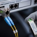
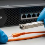
deploy with cleanliness and strain relief discipline
- Clean LC connectors using fiber-grade cleaning tools and inspect with a microscope or inspection scope.
- Use proper cable bend radius and strain relief so the connector is not stressed after cabinet closure.
- Label both ends and record which SFP serial number maps to which fiber pair for future maintenance.
monitor link and DOM telemetry during acceptance testing
If DOM is supported, we captured optical power and temperature readings during acceptance. We then stressed the link with normal production traffic and monitored for CRC errors and link state transitions. This step helped distinguish “bad optics” from “bad configuration,” because DOM telemetry often reveals gradual degradation long before complete failure.

Measured results: stability, error rates, and maintenance impact
After deployment and acceptance testing, the links remained stable through daily temperature cycles and repeated power-up events. We tracked link stability by monitoring interface status events and error counters at the switch and upstream aggregation layer.
For the multimode segment, the uplink maintained stable operation with zero link down events during a two-week observation window. CRC error counters remained at near zero under normal production load, and DOM readings stayed within the vendor’s expected ranges for optical power and module temperature. For the single-mode uplink, we observed similarly stable behavior with no recurring retransmission patterns attributable to physical layer issues.
Operational metrics the field team cared about
- MTTR impact: reduced mean time to restore links because optics mapping and DOM readings allowed quick isolation.
- Power cycle recovery: links came up reliably after controlled power interruptions with consistent receive power.
- Maintenance planning: recorded module serial numbers and telemetry enabled proactive replacement scheduling.
Pro Tip: In industrial cabinets, most “SFP incompatibility” complaints are actually connector cleanliness or insufficient optical margin that only appears under cold starts. Use an inspection scope and measure received optical power at acceptance; the received power trend is often a better early warning than link status alone.
Common mistakes and troubleshooting tips for Phoenix Contact SFP links
Even with correct selection, real-world failures happen. Below are the most common pitfalls we saw during industrial commissioning, along with root causes and practical fixes.
Link never comes up after installation
Root cause: wrong transceiver class for the port data rate, or swapped TX/RX fibers causing no receive signal. In some plants, patch panels are mislabeled, and the technician connects the wrong fiber pair.
Solution: confirm the FL SWITCH port supports the exact data rate (for example, 10G vs 1G). Then verify fiber directionality by checking TX-to-RX mapping end-to-end, and re-clean connectors before retesting.
Link flaps during temperature swings
Root cause: insufficient optical power margin, often due to excessive patch cord loss, dirty connectors, or aging splices. Temperature can change laser output and receiver sensitivity, pushing the link past its margin.
Solution: measure received optical power at multiple times (cold and warm). If margin is tight, replace patch cords, clean connectors again, and consider upgrading to a higher-budget transceiver type that matches the fiber standard and connector reality.
CRC errors rise gradually and then spike
Root cause: physical layer instability caused by intermittent connector contact, poor strain relief, or micro-bending in fiber routing near door hinges or cable trays.
Solution: inspect mechanical routing, ensure bend radius compliance, add strain relief, and verify connector seating. If DOM is available, correlate CRC spikes with DOM optical power dips to confirm the physical layer cause.
Selection criteria checklist: what engineers should decide first
Use this ordered checklist to reduce procurement risk and avoid expensive downtime. It is tuned for industrial deployments where field verification matters as much as datasheet claims.
- Distance and fiber type: confirm OM grade for multimode or SMF spec for single-mode, and use measured insertion loss.
- Data rate and wavelength: match the transceiver type to the FL SWITCH port requirements (for example, 850 nm for SX/SR, 1310 nm for LR).
- Switch compatibility: confirm Phoenix Contact FL SWITCH model support for the transceiver type; prefer modules listed in vendor guidance when available.
- DOM behavior: verify whether the switch reads DOM and whether the module provides consistent telemetry via SFF-8472.
- Operating temperature grade: choose industrial-rated modules that cover your cabinet ambient and internal heat rise.
- Vendor lock-in risk and spares strategy: evaluate third-party modules carefully, and standardize on a small set of proven part numbers for spares.
Cost and ROI note: what to budget for across the lifecycle
In typical industrial markets, a compatible Phoenix Contact SFP transceiver price can vary widely by data rate and reach. As a realistic planning range, many qualified SFP/SFP+ optics land in the approximate band of $50 to $250 per module, depending on whether you buy OEM-branded parts or reputable third-party equivalents. For 10G-class optics and longer reach, pricing often trends higher.
ROI comes from reducing downtime and shortening troubleshooting time. Even if a third-party module is cheaper upfront, the total cost can rise if it increases commissioning time, causes link flaps, or lacks consistent DOM telemetry that speeds root-cause analysis. From an operations perspective, maintaining a small, validated spares kit and recording module serial numbers can prevent repeated emergency purchases.
FAQ: Phoenix Contact SFP and FL SWITCH compatibility questions
Which FL SWITCH models work best with Phoenix Contact SFP modules?
Compatibility depends on the specific FL SWITCH model and port type. Always check the FL SWITCH datasheet and any transceiver guidance for the exact SFP data rate and optical interface. If you have a long-lived spare pool, standardize on part numbers that have documented success in your switch family.
Can I use third-party SFP modules with Phoenix Contact FL SWITCH?
Often yes, but you must validate against your port requirements, optical budget, and environmental constraints. Third-party DOM behavior and electrical timing can differ, which may affect how quickly the link stabilizes after power-up. Use measured received power and acceptance testing rather than relying solely on “spec match.”
What fiber measurements should I take before installing?
Measure end-to-end attenuation and verify connector insertion loss across the full path, including patch cords and splices. If possible, inspect connector end-faces and confirm fiber directionality (TX to RX mapping). This prevents most commissioning failures caused by insufficient margin and contamination.
Why do links flap only in cold weather?
Cold starts can reduce effective optical margin, and the link can cross the threshold where receiver sensitivity is no longer sufficient. Connector contamination effects can also become more pronounced when the system cycles. Correlate link flaps with DOM optical power trends to pinpoint the physical layer cause.
Does DOM telemetry help with troubleshooting?
Yes, if the FL SWITCH reads DOM reliably for your module. DOM can show optical power and module temperature, allowing you to distinguish between fiber loss, dirty connectors, and thermal stress. Use it during acceptance testing to establish baseline values for future comparisons.
How do I choose between multimode and single-mode for industrial plants?
Choose multimode for shorter distances within the same cabinet cluster when the fiber plant is OM3/OM4 and the budget supports it. Choose single-mode for longer inter-building runs or where fiber standards and splicing practices favor 1310 nm optics. In both cases, selection should be driven by measured loss and conservative margin, not only nominal reach.
If you want the fastest path to reliable deployment, start with a compatibility-first approach: match data rate and wavelength to your FL SWITCH ports, validate fiber loss with measurements, and enforce connector cleanliness during installation. For related planning, see fiber optic transceiver compatibility checklist to build a repeatable procurement and acceptance workflow.
Author bio: I have deployed industrial Ethernet fiber links in manufacturing and logistics environments, using SFP/SFP+ transceivers with measured optical budgets and DOM-based acceptance checks. I write field-oriented guidance grounded in IEEE Ethernet concepts and vendor documentation to help teams avoid avoidable commissioning downtime.