I have wired Peplink Balance routers into real sites where the “right” SFP still failed to train—usually because of optics reach, wavelength mismatch, or switch compatibility quirks. This guide helps network engineers and field techs plan and deploy Peplink fiber WAN using common SFP transceivers, with the operational details you need to avoid repeat truck rolls. You will also get a troubleshooting checklist based on the failure modes I have seen during link bring-up and DOM verification.
Prerequisites for a clean Peplink fiber WAN SFP deployment
Before you touch an optic, I like to confirm the physical layer constraints and the router interface expectations. On the bench, I verify the SFP type, connector cleanliness, and the fiber polarity plan. In the field, I also confirm that the site can support the module temperature range and that the fiber plant has enough margin for the intended reach.
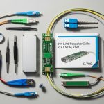
What you should have on hand
- Peplink Balance router model (confirm the WAN SFP interface type and whether it expects 1G SFP or another rate)
- One spare SFP per link direction for fast swap testing
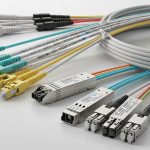
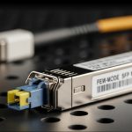
- Fiber jumpers with the correct connector (LC is most common for SFP)
- Polarity plan: either A-to-A/B-to-B or APC-style crossover depending on the patch panel labeling
- Cleaning kit (lint-free wipes plus appropriate solvent or gel cleaner)
- Optical power measurement tools when possible (a handheld OPM or OTDR from the vendor toolchain)
Reference standards and vendor docs to keep nearby
When you are validating compatibility, treat the optics as a standards problem first and a “brand match” problem second. The baseline behavior for Ethernet PHY over fiber is grounded in IEEE 802.3 for the corresponding speed and optical interface behavior. For transceiver characteristics and DOM interpretation, you will also want the module vendor datasheet and the router’s SFP compatibility guidance. [Source: IEEE 802.3] [[EXT:https://standards.ieee.org/standard/]]
Step-by-step: implement Peplink fiber WAN using SFP optics
Below is the numbered implementation path I use during deployments. Each step includes an expected outcome so you can stop early when something is off.
Identify the exact WAN rate and optical class
Start by confirming whether your Peplink Balance router port is configured for a specific Ethernet speed (commonly 1G for SFP in many WAN scenarios). Then decide between SX (multimode) and LX/LR (single-mode) based on the run length and fiber type in the building riser or outside plant.
Expected outcome: You can state the target data rate and whether you will use multimode (OM3/OM4) or single-mode (OS2) fiber before you order optics.
Choose wavelength and reach based on fiber type and loss budget
For multimode, 850 nm “SX” optics are typical. For longer runs and outside plant, 1310 nm “LX” or 1550 nm “LR” optics are common for single-mode. In practice, I calculate a simple link budget using typical fiber attenuation plus connector and splice loss, and I add a safety margin for aging and patch panel rework.
Expected outcome: Your selected module reach is greater than the actual run by a margin you can defend (I aim for at least a 3 to 6 dB cushion when measurements are available).
Verify SFP electrical compatibility and DOM behavior
Even when the wavelength matches, link training can fail if the module’s electrical characteristics don’t align with the router’s expectations. Check whether the router accepts digital optical monitoring (DOM) via the standard management interface. Many SFPs expose real-time values like transmit bias current, received power, and module temperature; the router may display link status even if DOM is unsupported, but alarms and logging can differ.
Expected outcome: The router recognizes the SFP (module present) and the interface shows operational link state when fiber is connected.
Plan polarity and patch panel mapping before you insert anything
With duplex fiber, direction matters. If you mix up transmit and receive fibers, the link may stay dark. I label patch cords at both ends before I go near the rack, and I document the mapping for future maintenance.
Expected outcome: You can connect fiber so that router transmit goes to switch or far-end receive, consistently across both ends.
Clean connectors and seat the SFP with the correct orientation
This is the step that saves hours. I clean both ends of the fiber patch and the SFP optical bores with the correct method, then I inspect under a scope if the site is high-value. For LC connectors, even a light film can reduce received power below threshold.
Expected outcome: When you insert the SFP and connect fiber, the interface begins link negotiation rather than staying at “down.”
Bring up the interface and confirm negotiated link parameters
On the router, confirm the WAN interface is configured for the correct speed/duplex mode if required. Many environments rely on auto-negotiation, but fiber optics can still behave differently than copper in edge cases. After link comes up, I verify counters and check for CRC errors or excessive retransmits.
Expected outcome: The link is stable, counters remain clean under light and then heavier traffic loads.
Validate performance under real traffic and document optics details
Once stable, I run a realistic test: sustained throughput close to the target WAN rate and a short loss/latency check. I also record DOM readings (if supported) and the final fiber mapping in the site notes so the next engineer does not guess.
Expected outcome: You have a repeatable record: module part number, wavelength, connector type, DOM status, and observed received power.

SFP options for Peplink Balance routers: multimode vs single-mode
In the field, the main decision for Peplink fiber WAN is whether your fiber plant is multimode or single-mode, and how much loss budget you can tolerate. Multimode SX at 850 nm is often cost-effective for campus links. Single-mode at 1310 nm or 1550 nm is the safer choice for long runs and outside plant where connectorization and splices are unpredictable.
Common module examples I have used or specified
- Cisco SFP-10G-SR for 10G multimode use cases (more common in 10G designs)
- Finisar FTLX8571D3BCL style optics for 1G multimode deployments (850 nm class)
- FS.com SFP-10GSR-85 and similar third-party SR optics when budget matters and the router accepts compatible optics
Note: exact part compatibility depends on your specific Peplink Balance model and port type. Always check the router’s documented SFP compatibility list or test in a controlled bench setup first.
Technical specifications comparison (typical SFP classes)
| Spec | Multimode SX (Typical) | Single-mode LX/LR (Typical) |
|---|---|---|
| Wavelength | 850 nm | 1310 nm (LX) or 1550 nm (LR) |
| Fiber type | OM3/OM4 multimode | OS2 single-mode |
| Connector | LC duplex (most common) | LC duplex (most common) |
| Reach class | Often a few hundred meters to ~300 m at 1G depending on OM type | Often 10 km+ depending on optic class (varies by datasheet) |
| DOM (digital monitoring) | Common; values vary by vendor | Common; values vary by vendor |
| Operating temperature | Typically commercial (0 to 70 C) or industrial variants (up to ~85 C) | Same ranges; pick industrial if exposed to heat |
| Power budget concept | Shorter reach, tighter loss tolerance | Long reach, more forgiving when fiber is clean and OS2 |

Selection checklist: decide the right Peplink fiber WAN SFP
When I am choosing optics for Peplink fiber WAN, I treat it like a procurement and reliability exercise, not just a “works on my bench” moment. This checklist is the order I typically use so the decision is fast and defensible.
- Distance and fiber type: measure or confirm the run length and whether the plant is OM3/OM4 or OS2
- Wavelength match: 850 nm for multimode SX, 1310/1550 nm for single-mode classes
- Connector and polarity: LC duplex, and a documented A-to-A vs crossover plan
- Switch and far-end compatibility: ensure the peer device supports the same speed and optic class
- DOM support and diagnostics: confirm whether the router reads DOM and logs thresholds
- Operating temperature: pick industrial-rated optics if the rack or outdoor enclosure runs hot
- Vendor lock-in risk: test third-party SFPs in advance; keep OEM spares when uptime is critical
- Budget and total cost: compare purchase price plus expected replacement cycle and troubleshooting time
Pro Tip: In field tests, I often see “mystery down links” traced not to the SFP itself but to connector contamination after a few manual disconnects. If you have DOM support, watch received power trends; a sudden drop after reseating usually means you cleaned the wrong side or you reused a dusty patch cord.
Common mistakes and troubleshooting for SFP WAN links
Even experienced teams hit predictable failure points. Here are the top issues I have personally debugged, with the root cause and the fix.
Failure point 1: Link stays down after installing a correct-looking SFP
Root cause: Transmit/receive polarity reversed on one end, or the patch panel uses inconsistent labeling. Solution: Swap the fiber pair at one end (not both) and confirm with a polarity map. If you can, use an OPM to validate received power when you move the patch cord.
Failure point 2: Intermittent drops under traffic load
Root cause: Received optical power marginal due to connector dirt, bend radius violations, or underestimated splice loss. Solution: Clean connectors, inspect under magnification, and re-terminate if needed. Verify bend radius compliance for the fiber jumper and check for damaged patch cords.
Failure point 3: Works in one direction but not the other
Root cause: Wavelength mismatch or using the wrong optic class (for example, pairing an SX multimode optic with a single-mode plant without conversion). Solution: Confirm both ends use the same wavelength and appropriate fiber type. Replace with the correct module class and validate link negotiation again.
Failure point 4: SFP is detected but router interface errors spike
Root cause: DOM thresholds or quality issues causing high BER, often from marginal signal levels or poor optical budget. Solution: Measure received power and compare to the module datasheet sensitivity. If within spec but errors persist, check the far-end configuration for speed forcing and verify the router WAN interface settings.

Cost and ROI: what SFP choices mean for Peplink fiber WAN TCO
Pricing varies by speed class and whether you choose OEM vs third-party. In many deployments, third-party SFPs (including reputable distributors) can run roughly $30 to $120 per module for common 1G/10G classes, while OEM-branded modules often cost more, sometimes $80 to $250 depending on support and warranty. TCO is not only the module price; it includes downtime risk, spare inventory, and troubleshooting labor when a “compatible” optic does not behave consistently.
ROI is best when you standardize on a small set of optics that match your fiber plant: one multimode SX option for OM3/OM4 sites and one single-mode LX option for OS2. I also factor expected failure rates: optics are usually reliable, but connector contamination and bad patching dominate real-world incidents. If your operation runs hot racks or outdoor enclosures, paying for industrial temperature rating can prevent repeat failures and reduce truck rolls.
FAQ: Peplink fiber WAN SFP questions engineers ask
What SFP types are typically used for Peplink fiber WAN?
Most deployments use SFP optics that match the WAN port speed and the fiber plant. Common patterns include 850 nm SX for multimode campus runs and 1310 nm LX for longer single-mode links. Always confirm the exact Peplink Balance model’s WAN interface requirements and test compatibility.
Can I use third-party SFP modules with Peplink Balance routers?
Often, yes, but it is not guaranteed across every optic and every router revision. I recommend bench testing a few candidates and validating DOM behavior if available. Keep OEM spares for critical sites until you have confidence with a specific part number.
How do I choose between multimode and single-mode for a fiber WAN run?
Use multimode if the distance is short and you have OM3/OM4 fiber with a comfortable loss budget. Choose single-mode when you are dealing with longer runs, outside plant, or uncertain splice quality. If you are unsure about the fiber type, check the fiber jacket marking and verify with onsite documentation.
Why does the link come up sometimes and fail after reseating?
That pattern strongly suggests connector contamination or a polarity change caused by re-patching. Clean both sides of the connection and inspect with magnification if you can. Also verify that the patch cords and jumpers remain within bend radius after you re-seat them.
What should I check with DOM monitoring?
If the router reads DOM, monitor received optical power, transmit bias current, and module temperature. Compare values to the module datasheet ranges. If DOM shows values drifting toward the threshold, proactively replace the optic or clean and re-check the fiber path.
Do I need an OTDR for Peplink fiber WAN troubleshooting?
An OTDR is not always required, but it is valuable when you have persistent margin issues or unclear splice history. For many problems, an optical power meter plus connector inspection resolves the root cause faster. Use OTDR when you must locate high-loss events along the fiber route.
If you want predictable Peplink fiber WAN behavior, standardize your optics by fiber type, document polarity, and treat connector cleaning as part of the engineering process. Next, review how to size fiber WAN link budgets to turn “it should work” into a measurable optical budget before you roll a truck.
Author bio: I am a field-focused network writer who documents real deployments of fiber WAN links, including optics selection and bring-up procedures. I have spent years translating vendor datasheets and IEEE behavior into practical checklists for on-site engineers.