AI workloads are reshaping network traffic patterns, turning “best effort” designs into latency- and reliability-critical systems. This article helps network architects, DC engineers, and field teams integrate optical technologies into AI-ready fabrics—covering link budgets, transceiver selection, and operational pitfalls. You will get practical decision checklists, real deployment context, and guidance aligned to Ethernet physical-layer expectations such as IEEE 802.3 and vendor datasheet constraints. Update date: 2026-04-30.
Why AI changes the optics requirements in your network
When AI training and inference scale, the dominant traffic shifts from predictable north-south flows to bursty east-west communication across many racks. That increases sensitivity to congestion, link errors, and any optical mismatch that causes retransmissions. In practice, the physical layer must support higher throughput per port, consistent signal integrity, and predictable optics behavior under temperature and power constraints.
Optical technologies address this by enabling higher data rates over fiber with low electromagnetic interference, stable latency, and scalable cabling. But AI-ready designs also demand operational maturity: DOM/telemetry visibility for early fault detection, deterministic optics provisioning, and careful attention to reach and connector cleanliness. For standards grounding, Ethernet PHY and optics expectations are discussed across IEEE 802.3 families for 25G, 100G, 200G, and 400G operation. [Source: IEEE 802.3 overview, IEEE Standards Association]. anchor-text: IEEE 802.3 standards
Where optical links become a bottleneck for AI fabrics
Even when switch ASICs can handle line-rate forwarding, an optics layer can throttle performance via marginal links, excessive BER, or frequent training retries. AI clusters often run dense leaf-spine or Clos fabrics; if one ToR uplink experiences higher error rates, it can trigger TCP retransmits and application-level stalls. The result is not just lost throughput, but also increased tail latency that harms distributed training synchronization.
What “AI-ready” means at the optical layer
In field terms, AI-ready usually means: high link availability, predictable reach (no “works on my bench” surprises), and telemetry-driven operations. Engineers typically verify transceiver compatibility with the exact switch vendor part numbers and ensure that optics are within the supported temperature range and power class. DOM support also matters for automation, because AI operations teams want to correlate optical health with job performance and error counters.
Pro Tip: In many deployments, the biggest “mystery” link failures come from fiber end-face contamination and not from the transceiver itself. Use an inspection scope after any patch change, and treat connector cleaning as part of the change-control workflow. This prevents intermittent CRC spikes that look like congestion but originate at the optics physical layer.
Core optical technologies for AI: from 25G to 400G
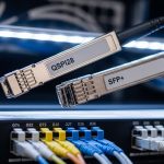
AI fabrics commonly start with 25G or 100G per server and scale to 200G or 400G for spine uplinks. The choice is driven by switch port density, cabling architecture, and the physical distance between endpoints. Optical technologies are typically implemented through pluggable transceivers (SFP, SFP28, SFP56, QSFP+, QSFP28, QSFP56, OSFP, and CFP2/CFP4 families depending on the platform) and fiber types such as OM3/OM4/OM5 multimode and OS2 single-mode.
The table below summarizes representative options engineers compare when building AI-ready networks. Always verify exact compliance with your switch model and the relevant IEEE 802.3 clause for the target speed and reach. [Source: vendor transceiver datasheets and IEEE 802.3 physical layer documents].
| Optical technology (example module) | Data rate | Wavelength | Typical reach | Fiber type | Connector | Operating temp (typ.) | Common use in AI fabrics |
|---|---|---|---|---|---|---|---|
| Cisco SFP-10G-SR (legacy reference) | 10G | 850 nm | ~300 m (MM) | OM3/OM4 | LC | 0 to 70 C | Historical baselines and test labs |
| FS.com SFP-10GSR-85 (example vendor third-party) | 10G | 850 nm | ~300 m (MM) | OM3/OM4 | LC | 0 to 70 C | Multimode server links where supported |
| Finisar FTLX8571D3BCL (example 10G SR module) | 10G | 850 nm | ~300 m (MM) | OM3/OM4 | LC | 0 to 70 C | Benchmarked compatibility and optics health |
| Typical 100G SR4 (4-lane multimode) | 100G | ~850 nm | ~100 m (MM, varies by spec) | OM4/OM5 | LC | 0 to 70 C | Leaf-to-spine in short-reach designs |
| Typical 400G FR4/DR4 (single-mode variants) | 400G | 1310/1550 nm bands (varies) | 2 km to 10+ km (varies) | OS2 SMF | LC or MPO (by module) | -5 to 70 C (varies) | Spine uplinks and metro extension |
Because module categories vary widely by vendor, use the table as a framework—not a substitute for your exact datasheet and switch compatibility matrix. For switch vendors, the most reliable reference is the “supported optics” document tied to your exact switch SKU and software version.

Selection criteria for integrating optical technologies with AI fabrics
Engineers typically choose optics by balancing distance, performance margins, and operational risk. For AI-ready networks, the goal is to minimize retransmissions and avoid “marginal links” that pass initial tests but degrade after temperature swings or connector wear. The selection process should also consider automation needs, since AI operations often correlate telemetry with job scheduling.
Decision checklist engineers use in the field
- Distance and reach class: Confirm the expected link distance including patch panels and slack. Validate that the chosen optics meet the vendor reach specification for the exact fiber type (OM3 vs OM4 vs OM5, or OS2).
- Budget and margin: Use the link budget including connector loss, splice loss, and any patch cords. For multimode, account for bandwidth limits and modal dispersion; for single-mode, ensure proper wavelength alignment.
- Switch compatibility: Verify optics are supported on your switch model and firmware. Check whether the platform requires specific transceiver vendor IDs or firmware behavior.
- DOM and telemetry: Ensure Digital Optical Monitoring is enabled and that the platform exposes thresholds (temperature, laser bias current, received power, and alarms).
- Operating temperature and airflow: Validate the optics temperature range against the rack’s airflow profile. If you have hot aisle containment, use measured inlet temperatures rather than nameplate assumptions.
- Fiber connector standards and cleanliness: Confirm LC or MPO polishing type and that your maintenance process includes inspection after changes.
- Vendor lock-in risk and procurement strategy: Decide whether OEM-only optics are acceptable or whether third-party modules are acceptable with a qualification plan and RMA process.
- Change-control and testing: Plan acceptance tests that include error counters under load, not just link-up verification.
Multimode vs single-mode in AI-ready designs
Many AI clusters prefer multimode for short-reach server links due to lower cost and easier handling within data center spans. Single-mode becomes attractive for longer leaf-to-spine runs, campus extension, or when you want to standardize on one fiber plant. The tradeoff is that multimode is more sensitive to bandwidth constraints and connector quality, while single-mode demands strict wavelength and alignment discipline.

Operational integration: telemetry, automation, and fault containment
AI environments benefit from tight feedback loops. When an optics alarm triggers, the network team needs to know whether the issue is rising received power degradation, temperature drift, or a connector problem causing intermittent errors. DOM data can feed dashboards and alerting rules, enabling faster isolation and reducing training disruption.
What to monitor during AI job peaks
At minimum, monitor link up/down events, CRC and FCS error counters, optical receive power (Rx), transmit power (Tx), and temperature. For higher assurance, correlate these with switch ASIC interface counters and platform logs. If you deploy with automation, connect telemetry to incident workflows so that optics faults create tickets with the correct likely root cause category (for example, “laser bias drift” vs “link margin reduction”).
Compatibility caveats that matter
Even when a transceiver is “technically compatible” at the electrical standard level, platform behavior can differ. Some switches require specific DOM alert threshold mappings, and some may reject optics with mismatched vendor identifiers or unsupported speed modes. Always test in a staging rack that mirrors your airflow, patching, and firmware version—especially before scaling optics procurement across many spines and leaves.
Pro Tip: For AI clusters, set alert thresholds on DOM received power with hysteresis and time windows. A one-second spike can be a benign event (like a brief patch disturbance), while a sustained drift over 10 to 20 minutes often indicates gradual connector degradation or fiber aging.
Common mistakes and troubleshooting in optical technologies deployments
Most optical problems are solvable, but only if teams use the right diagnostic sequence. Below are common failure modes seen in AI-ready builds, along with root causes and fixes that field engineers can execute quickly.
Link comes up, then errors spike during load
Root cause: Dirty connectors or damaged fiber end faces causing intermittent high loss, which increases BER under stress. Solution: Inspect and clean both ends with approved cleaning tools, verify connector polish type, and re-seat transceivers firmly. Then run a sustained traffic test while watching Rx power and CRC counters. If you have MPO, confirm correct keying and polarity.
Random link flaps after thermal changes
Root cause: Optics operating near temperature limits due to blocked airflow, misrouted cables, or hot-spot formation behind transceivers. Solution: Measure inlet air temperatures at the rack, confirm that optics are within the vendor temperature range, and improve airflow paths. Re-check that fan trays and venting are functioning, then validate with a load test at peak ambient.
“Supported optics” mismatch or silent performance downgrade
Root cause: Transceiver not approved for the specific switch SKU or firmware version, leading to partial feature support or unexpected speed negotiation behavior. Solution: Cross-check the switch vendor compatibility list, update switch software if the vendor recommends an optics compatibility fix, and replace the module with an approved part for the same reach class.
Reach failures that appear only after cutover
Root cause: The measured fiber path length includes patch cords, jumpers, and splices that were not included in the planning model. Solution: Recalculate end-to-end loss with actual as-built lengths, count connectors and splices, and verify that the optics budget includes adequate margin. If needed, shorten the fiber path or change to a higher-reach optics option.

Cost and ROI: balancing OEM optics, third-party modules, and TCO
Optics pricing varies by speed class, reach, and whether the module is OEM-branded or third-party. In many data centers, OEM transceivers cost more upfront, but they can reduce integration risk due to tighter platform qualification. Third-party modules often lower purchase price, yet require a qualification plan and a clear RMA policy to avoid prolonged downtime during AI job windows.
A realistic TCO view includes: hardware cost, labor for installation and troubleshooting, downtime cost during failures, and the operational overhead of managing compatibility. For example, OEM optics might carry a premium that is justified when your failure rate directly impacts training schedules or when your operating model cannot tolerate extended troubleshooting cycles. Conversely, third-party optics can be cost-effective when you have a mature test harness, spare inventory planning, and standardized cleaning and inspection procedures.
Practical budgeting ranges to use in planning
As a planning heuristic (prices vary significantly by region and volume), 25G and 100G pluggables often range from tens to a few hundred dollars each, while 200G and 400G modules can cost several hundred to over a thousand dollars per unit depending on reach and vendor. The ROI improves when you reduce incident duration and avoid rework. Measure this using your historical mean time to repair and mean time between failures, then model how optics telemetry reduces detection time.
For authoritative guidance on performance and limits, rely on vendor datasheets and the relevant Ethernet PHY requirements; for standards framing, consult IEEE 802.3. [Source: vendor datasheets and IEEE 802.3 physical layer references]. anchor-text: IEEE resources
FAQ
Which optical technologies are most common for AI training clusters?
Most deployments use a mix of short-reach multimode optics for server and ToR connectivity and single-mode optics for longer leaf-spine or metro extension. You typically see 25G or 100G at the edges and 200G or 400G for uplinks, depending on switch generation and fabric design.
How do I confirm compatibility between transceivers and my switch?
Start with the switch vendor’s supported optics list for your exact model and firmware version. Then validate in a staging rack with the same patching and airflow, confirming that DOM telemetry fields and threshold alarms appear as expected.
What should I monitor in DOM to prevent AI job disruptions?
Track Rx power, Tx power, temperature, and alarm states, and correlate them with CRC/FCS error counters and interface error statistics. Set alerts using time-based windows so you catch sustained degradation rather than transient blips.
Is multimode still a good choice for optical technologies in data centers?
Yes, for short reaches where OM4 or OM5 cabling is installed and connector cleanliness is controlled. Multimode can be cost-effective, but it is more sensitive to launch conditions, patch cord quality, and end-face contamination.
What are the fastest troubleshooting steps when a link repeatedly flaps?
First inspect and clean both fiber ends, then re-seat the transceiver and verify connector polarity and keying for MPO. Next check rack airflow and ambient inlet temperature, and finally confirm that the optics is supported by the switch at your running software version.
Should we standardize on OEM optics or allow third-party modules?
Standardization reduces operational complexity and compatibility risk, which can matter during AI scaling. Third-party modules can be viable when you run qualification tests, keep spares, and have a strong RMA and testing process to avoid extended downtime.
Optical technologies are not just components in an AI network; they are operational control points that affect latency, error rates, and fault detection speed. If you want a practical next step, review optical fiber cabling best practices and align your connector hygiene, patching, and acceptance testing to your fabric design.
Author bio: I have deployed and troubleshot multi-rack Ethernet fabrics using pluggable optics, fiber inspection workflows, and DOM telemetry automation in production data centers. My work focuses on measurable link margin, standards-aligned physical layer validation, and operational playbooks that reduce AI training disruption.