Edge computing deployments often fail in the last mile: the rack ships, the fiber is terminated, and then optics compatibility, temperature limits, or reach mismatches quietly derail go-live. This article helps network engineers and field technicians select optical modules that match real edge constraints—limited power, harsh thermals, short patch cords, and vendor-specific transceiver behavior. You will get a practical decision checklist, a troubleshooting playbook, and spec comparisons grounded in common Ethernet standards and vendor datasheets.
Edge computing link reality: what changes versus core data centers?
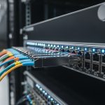
In central data centers, you can usually standardize on a single transceiver family because thermal headroom and power budgets are generous. At the edge—industrial sites, retail back rooms, utility substations, and telco edge huts—your optics must survive temperature swings, vibration, and long-term optical aging while staying within strict link budgets. Most edge links are still Ethernet (IEEE 802.3 families for 1G/10G/25G/40G/100G), but the physical layer details matter more: patch cord length, connector cleanliness, and whether your switch validates DOM (Digital Optical Monitoring).
What engineers measure before buying
- Distance and fiber type: measure from switch to edge router using OTDR results if available; confirm single-mode versus multi-mode.
- Connector and patching: verify LC vs MPO, end-face condition, and whether you are using pre-terminated assemblies.
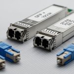
- Switch transceiver rules: confirm supported form factors and speed (SFP, SFP28, QSFP+, QSFP28, QSFP56) and whether “third-party” optics are filtered.
- Power and thermal constraints: check chassis airflow; validate module operating temperature range for the edge cabinet.
For standards alignment, reference IEEE 802.3 for the line-rate and optical interfaces, then rely on vendor datasheets for reach, wavelength, and DOM behavior. For example, short-reach Ethernet optics commonly target 850 nm (MMF) for SR variants, while long-reach variants commonly target 1310 nm or 1550 nm (SMF) depending on the rate.

Optical module selection for edge: SR vs LR, SMF vs MMF, and wavelength choices
Edge networks typically mix short internal runs (server-to-switch, switch-to-edge gateway) with longer carrier backhaul (switch-to-POP). That means you may need both short-reach and long-reach optics, plus careful fiber-type matching. A common failure mode is buying an SR module for a single-mode link or assuming “reach” alone covers connector and splice losses.
Quick spec comparison engineers use in edge procurement
Below is a compact comparison of widely deployed Ethernet optical modules. Always confirm the exact ordering part number and DOM support in your switch compatibility matrix.
| Module type | Data rate | Wavelength | Fiber | Typical reach | Connector | Operating temp range | DOM / monitoring |
|---|---|---|---|---|---|---|---|
| Cisco SFP-10G-SR | 10G | 850 nm | MMF (OM3/OM4) | Up to 300 m (OM3) | LC | 0 to 70 C (varies by revision) | Digital DOM supported |
| Finisar FTLX8571D3BCL (example 10G SR) | 10G | 850 nm | MMF (OM4 common) | Up to 400 m (OM4 class) | LC | -40 to 85 C (typical for industrial grades) | DOM supported |
| FS.com SFP-10GSR-85 (example 10G SR) | 10G | 850 nm | MMF | Up to 400 m (OM4 common) | LC | -40 to 85 C (model dependent) | DOM supported |
| Cisco QSFP-40G-SR4 (example 40G SR4) | 40G | 850 nm | MMF | Up to ~100 m on OM3 (rate dependent) | MPO | 0 to 70 C (varies) | DOM supported |
| Long-reach SMF example (rate dependent) | 10G to 100G | 1310 or 1550 nm | SMF | Up to tens of km (model dependent) | LC | -40 to 85 C (industrial variants exist) | DOM supported |
These entries illustrate typical patterns: SR optics use 850 nm and MMF, while LR optics use SMF at 1310/1550 nm. Exact reach depends on the fiber grade (OM3 vs OM4), link loss budgets, and the transceiver’s transmit power and receiver sensitivity.
For authoritative baseline requirements, consult IEEE 802.3 for the optical interface definitions and vendor datasheets for actual link parameters. If you want a vendor-neutral starting point for transceiver behavior, see IEEE 802.3 and Cisco optics and compatibility resources.
Pro Tip: In edge cabinets, DOM pass/fail is often the real “compatibility” gate. Even if a module matches wavelength and reach, a strict switch may reject optics due to DOM vendor ID or threshold settings, so validate with a two-port test before scaling deployment.
Deployment blueprint: a realistic edge case with numbers and outcomes
Consider a 3-tier edge rollout for a retail chain: each site has a leaf gateway switch connecting to an on-prem compute node and uplinking to a regional POP. At each store, a 48-port 10G ToR switch aggregates uplinks to a 2-port 10G router, and server patching uses short LC runs totaling 20 m on OM4. The uplink to the POP is 6 km over single-mode fiber with a measured end-to-end loss of 2.8 dB including splices and connector mated loss.
In this scenario, a technician uses 10G SR (850 nm, MMF, LC) for the store internal runs because the patch cords and transceivers are within the OM4 reach envelope and offer simpler installation. For the 6 km uplink, they select a 10G LR-class SMF (1310 nm, LC) module with a link budget that includes margin for aging and cleaning variability. After installation, they verify link stability by checking optical power readings via DOM (for example, verify receive power is within the vendor’s recommended range) and confirm the switch reports “link up” without CRC spikes. This exact approach prevents the most common edge failure: choosing optics based on “max reach” marketing numbers rather than measured loss and switch acceptance behavior.

Selection criteria checklist: the order that prevents rework
Edge deployments move fast, but rework is expensive. Use this ordered checklist so you eliminate the highest-probability incompatibilities first.
- Distance and fiber type: confirm MMF vs SMF and the measured loss; do not rely on “typical reach” alone.
- Data rate and lane mapping: ensure your switch port supports the exact rate (10G vs 25G vs 40G) and breakout mode, if applicable.
- Connector format: LC vs MPO/MTP; verify polarity requirements for MPO and whether your patching uses keyed connectors.
- Switch compatibility and DOM behavior: check the switch vendor’s supported transceiver list; confirm DOM is read and thresholds are acceptable.
- Operating temperature and mechanical stress: select industrial-grade optics when cabinets see extended heat or cold; confirm thermal cycling survivability.
- Power and budget: validate host power rails; ensure module power draw aligns with the chassis design margin.
- Vendor lock-in risk: if third-party optics are required for cost, perform a staged rollout and keep spare units matched by part number and revision.
- Compliance and safety: verify laser class labeling and regulatory compliance listed in datasheets for your region.
When you follow this order, you reduce the chance that you discover incompatibility only after remote sites are already installed. For standards context, the electrical and optical behavior of Ethernet PHYs is anchored in IEEE 802.3, while the optical performance and monitoring are defined in each transceiver’s datasheet and in the host’s diagnostic firmware.
Common pitfalls and troubleshooting tips in the field
Even well-chosen optics can fail in edge environments. Below are concrete mistakes that field teams repeatedly encounter, along with root causes and fixes.
Link fails or flaps after installation
Root cause: contaminated connectors or poor mating pressure, especially with rapid “plug and ship” workflows for edge sites. This can increase insertion loss and cause receiver instability.
Solution: clean using lint-free wipes and approved cleaning tools; inspect with a fiber microscope; re-terminate if end-face damage is present. Re-test with a known-good module pair before blaming the optics.
Wrong fiber type purchased (MMF vs SMF)
Root cause: ordering an SR module for a single-mode uplink (or an SMF module for MMF), sometimes because the purchasing form lacks a clear fiber-type field.
Solution: confirm fiber core type and labeling at the patch panel; verify using OTDR or at least confirm the cable jacket markings. Then swap modules to the correct wavelength and fiber class.
“DOM present” but alarms persist (high BER, CRC errors)
Root cause: receive power out of vendor-recommended range due to connector/splice loss, patch cord mismatch, or an optics pair with tighter sensitivity than expected.
Solution: read DOM metrics (Tx bias, Rx power, temperature) and compare to the module datasheet thresholds. If Rx power is low, improve optical cleanliness and reduce jumpers; if needed, choose an LR-class module or a variant with higher sensitivity.
Switch rejects third-party optics entirely
Root cause: the host switch enforces a compatibility list or DOM vendor ID policy, which can be strict depending on firmware.
Solution: verify in a lab with the exact switch model and firmware version; if needed, use OEM modules or a third-party brand explicitly validated by the switch vendor. Keep a small pilot cohort before scaling.

Cost and ROI: how to budget optics without gambling
Pricing varies by rate, reach, and grade, but a realistic range for common edge optics is: 10G SR modules often fall in the broad range of roughly $50 to $250 each depending on brand and temperature grade; 10G LR SMF modules typically cost more, often around $150 to $600. QSFP optics for 40G/100G can be significantly higher, and industrial-grade temperature variants cost more than standard commercial parts.
For TCO, include not just purchase price but also downtime risk, spares logistics, and the cost of testing at each staging batch. OEM optics may reduce failure and compatibility friction, but third-party optics can be cost-effective when you enforce a validation process and standardize part numbers. In edge deployments, where shipping delays can be measured in days and remote site access can be expensive, the ROI often favors optics that are “deployable now” with predictable compatibility and robust thermal performance.
To ground expectations, consult vendor datasheets for optical power, sensitivity, and DOM threshold behavior, and use switch vendor compatibility guidance where available. For additional credibility on Ethernet and interface definitions, see IEEE Standards.
FAQ: choosing optical modules for edge computing
Which optical modules fit edge deployments most often?
Most edge networks start with 10G SR (850 nm, MMF) for short in-cabinet runs and use SMF LR (1310 nm or 1550 nm) for longer uplinks. The exact choice depends on your fiber type, measured loss, and switch port support.
How do I confirm DOM compatibility with my switch?
Check the switch’s transceiver compatibility documentation and run a staged test with the exact module part number. In the field, validate that the switch reads DOM successfully and that optical alarm thresholds remain within the datasheet-recommended operating region.
Do I really need OTDR for every edge site?
If you have reliable fiber records and short, well-managed patch runs, you may not need OTDR for every connector. For long uplinks or when documentation is uncertain, OTDR is strongly recommended because it reveals hidden splice loss and fiber defects that “reach” claims cannot cover.
What are the biggest causes of optical link instability at the edge?
Common causes include contaminated connectors, incorrect fiber type, polarity or MPO mapping issues, and selecting optics with insufficient optical margin for the actual measured loss. DOM metrics combined with CRC and error counters help you pinpoint whether the issue is optical power, temperature, or compatibility.
Are third-party optical modules safe to use?
They can be safe and cost-effective, but only when you validate compatibility with the exact switch model and firmware version. Standardize part numbers, keep a pilot rollout plan, and maintain spares matched by revision to reduce “mystery incompatibility” during remote replacements.
How do temperature extremes affect optical module choice?
Temperature impacts laser bias stability, receiver sensitivity, and DOM-reported thresholds. For edge cabinets with harsh climates, choose modules with an appropriate industrial temperature range and verify the host airflow and cabinet thermal design.
Choosing the right optical modules for edge computing is mostly about matching specs to measurable reality: distance, fiber type, connector cleanliness, DOM behavior, and thermal constraints. If you want a related next step, review fiber optic transceiver compatibility to tighten your procurement and staging workflow.
Author bio: I design and validate network optics UX for field deployments, focusing on compatibility, observability, and operational reliability. I have supported real staging labs with DOM threshold checks, link-budget verification, and switch-specific transceiver constraints across multi-site rollouts.