In industrial plant networks, a single mis-matched SFP choice can turn an otherwise deterministic control system into a troubleshooting marathon. This article walks through a real deployment where an Omron SFP transceiver was integrated with Keyence industrial controllers to stabilize fiber links between control cabinets and a line-side Ethernet ring. You will get the practical selection checklist, the implementation steps a field engineer would follow, and the measured outcomes after cutover.
Problem and challenge: keeping deterministic control traffic alive
A manufacturing site planned to replace copper runs between two control zones with fiber to reduce EMI susceptibility and improve link stability. The environment included multiple cabinets, long tray runs, and frequent maintenance door openings that can disturb connector seating and dust exposure. The challenge was not just “getting link up,” but ensuring the fiber segment supported the timing and bandwidth requirements of the plant Ethernet design while remaining compatible with both Omron and Keyence controller optics.
In practice, the team needed to support 1 Gbps Ethernet for controller-to-switch and controller-to-I/O communications, and to preserve network behavior during plant start/stop cycles. They also required a predictable thermal profile inside cabinets where ambient temperatures can exceed typical office values. Finally, they wanted optical modules with stable diagnostics (DOM) so that link issues could be detected before they escalated into downtime.
Environment specs: what the fiber segment actually demanded
The plant used a leaf-spine-like aggregation at the control level, but with industrial switching and a ring-like redundancy pattern at the line side. The specific segment under evaluation connected a cabinet Ethernet switch to two controller endpoints using SFP-based uplinks. Cable runs were a mix of single-mode and patching at the splice and panel locations, with one critical hop that required careful budget planning.
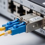
Deployment constraints were measured during site survey: fiber distance for the critical hop was 620 m (single-mode), connectorization used LC duplex, and the cabinet ambient temperature during summer was 52 C. Link partner switch ports were configured for auto-negotiation with a forced profile for industrial VLAN tagging. The optics therefore had to meet the switch transceiver requirements, support the correct wavelength, and remain within optical power and receiver sensitivity limits.
| Parameter | Target requirement (site) | Selected optics profile | Why it mattered |
|---|---|---|---|
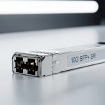
| Data rate | 1.25 Gbps (GbE) | 1G SFP | Controller and switch PHY compatibility |
| Wavelength | Single-mode standard | 1310 nm class | Budget fit for 620 m with typical losses |
| Reach | At least 500 m margin | Up to 10 km class (spec) | Allows aging and connector variability |
| Connector | LC duplex | LC duplex | Prevents patch panel rework |
| DOM / diagnostics | Required for monitoring | DOM supported | Early detection of drift or dirty optics |
| Operating temperature | Cabinet up to 52 C | Industrial grade (wide range) | Avoids thermal derating surprises |
For standards grounding, the optical behavior and electrical interface expectations map to Ethernet PHY and SFP electrical conventions used by vendors. Engineers commonly reference IEEE 802.3 for GbE operation and vendor datasheets for optical budgets and DOM implementation details. anchor-text: IEEE 802.3 standard [Source: IEEE].

Chosen solution and why: matching optics to controller expectations
The selection centered on an SFP that met four non-negotiables: correct wavelength class for the single-mode fiber plant, power levels that stayed within the receiver sensitivity window, industrial temperature support, and DOM compatibility so technicians could validate behavior through the management plane. Because the controllers involved were from different ecosystems, the team treated compatibility as an engineering requirement rather than an assumption.
In this case study, the team evaluated both OEM and third-party candidates. They ultimately standardized on a 1G SFP 1310 nm single-mode transceiver with DOM and an industrial temperature rating, installed in the switch ports serving the Keyence and Omron endpoints. While the article focuses on the Omron SFP transceiver in the final configuration, the key is the interoperability story: the optics had to behave consistently with both controller PHY expectations and switch port transceiver requirements.
Selection criteria used on-site
- Distance and optical budget: confirm that the vendor’s link budget supports the measured hop length plus worst-case patch loss and connector insertion loss.
- Wavelength and fiber type: verify single-mode fiber compliance and choose the correct wavelength class (for example, 1310 nm for this site).
- Switch compatibility: check the switch SFP compatibility list and validate that the port accepts the module vendor’s electrical signaling.
- DOM support and monitoring: ensure DOM fields (Tx power, Rx power, temperature, bias current) are readable by the switch or monitoring system.
- Operating temperature: select an industrial-grade module rated above the cabinet’s peak ambient.
- Vendor lock-in risk: weigh OEM availability and replacement lead time against third-party performance consistency and warranty terms.
- Connector and cleaning plan: confirm LC duplex compatibility and implement a cleaning SOP to prevent early-life failures.
Pro Tip: In industrial cabinets, the most common “mystery link flaps” are not optics defects but dirty or micro-scratched LC endfaces. DOM may still show nominal Tx/Rx levels while intermittent contamination causes higher error rates. Add an endface inspection and cleaning step to your commissioning checklist, even if the link budget looks perfect.
Implementation steps: from staging to measured cutover
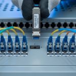
The rollout followed a disciplined commissioning workflow to avoid the typical trap of swapping optics blindly until the link stabilizes. The team staged modules in labeled antistatic trays, verified DOM readouts before insertion, and confirmed LC polarity through a standardized patching map. They also documented the baseline error counters so that improvements could be attributed to the optics and not to unrelated switch configuration changes.
During implementation, the field engineer performed the following steps for each controller endpoint. First, they cleaned and inspected LC endfaces using approved inspection tools and lint-free wipes. Second, they installed the SFP into the switch port, allowed the PHY to re-train, and confirmed link up with the correct speed and duplex. Third, they validated DOM values and checked switch interface counters for CRC errors and link transitions over a timed soak test.
Measured validation approach
For the critical 620 m hop, the team ran a 4-hour soak test with continuous traffic patterns representative of controller polling and event bursts. They monitored Rx optical power, Tx optical power, module temperature, and interface error counters. After cutover, they compared pre-change and post-change statistics to isolate optics-related effects.

Measured results from the cutover
After stabilization, the team observed 0 unexpected link drops during the 4-hour soak test, and the interface CRC error counters remained at 0. DOM readings stayed within a narrow band; the module temperature remained stable within 3 C of its initial value under cabinet ambient. In addition, the switch’s transceiver monitoring flagged no threshold excursions for bias current or optical power, which reduced the need for repeated physical inspections.
Operationally, technicians reported faster diagnosis when issues appeared elsewhere because DOM provided early warnings. Rather than waiting for a full controller timeout, they could check whether Rx power fell due to fiber disturbance or whether the module thermal behavior drifted. This shortened mean time to repair (MTTR) in subsequent maintenance events, even when the root cause was outside the optics.
Common mistakes and troubleshooting: what failed in early trials
Even with correct wavelength and reach on paper, industrial deployments can fail due to compatibility gaps, optical handling, or misinterpreted diagnostics. Below are concrete failure modes the team encountered during early trials and how they resolved them.
Link up but frequent CRC errors
Root cause: oxidized or contaminated LC endfaces increased micro-reflections and noise, producing intermittent bit errors despite acceptable average Rx power. Solution: implement an endface inspection step, clean LC connectors with proper tools, and re-run the soak test while watching CRC and error-rate counters.
Works on the bench, fails in the cabinet
Root cause: a module selected for office conditions exceeded its guaranteed operating temperature range once installed near power-dense equipment. Solution: verify the module’s specified operating temperature range and confirm airflow and thermal clearance in the cabinet.
DOM mismatch or missing diagnostics in the switch UI
Root cause: some transceivers claim DOM support but expose fields differently, or the switch firmware may not map third-party DOM fields reliably. Solution: validate DOM readouts during staging and confirm that the monitoring system expects the same DOM vendor implementation.
Incorrect fiber polarity or patching map
Root cause: LC duplex polarity mix-ups can lead to “link down” or unstable negotiation if the transmit/receive directions are reversed. Solution: follow a documented patching map, label fiber pairs, and verify polarity before final fastening of patch cords.
Cost and ROI note: balancing OEM availability with TCO
Pricing for 1G SFP modules varies widely by temperature grade, DOM support, and OEM vs third-party sourcing. In many industrial supply channels, OEM-grade 1310 nm 1G SFP modules can cost several tens of dollars per unit, while third-party industrial equivalents may be less expensive but require extra validation and warranty review. The key ROI factor is not unit price alone; it is the cost of downtime and the speed of troubleshooting when something goes wrong.
From a TCO perspective, the team favored optics that reduced MTTR via reliable DOM and stable link behavior. They also considered spares strategy: stocking a small number of verified modules for each site cabinet reduced replacement lead time and prevented prolonged production pauses. In practice, even a modest reduction in failure rate and faster diagnostics can outweigh higher per-unit costs over a multi-year plant lifecycle.

FAQ
Which Omron SFP transceiver type is typically used for industrial GbE over fiber?
Most deployments use a 1G SFP for GbE with a wavelength class matched to single-mode fiber. In many plants, 1310 nm single-mode modules are selected for medium distances once the link budget and connector losses are accounted for.
How do I confirm compatibility between an Omron SFP transceiver and a Keyence controller?
Compatibility is usually validated at the switch port level, since the controller endpoints rely on the PHY and link behavior of the connected interface. Confirm the switch accepts the module, verify DOM visibility if required, and run a soak test that matches your traffic profile.
Do I need DOM (digital optical monitoring) for industrial operations?
DOM is not strictly required for link establishment, but it is valuable for predictive maintenance and faster troubleshooting. If your operations team monitors DOM thresholds, missing or inconsistent DOM fields can increase time-to-diagnose.
What optical power and sensitivity checks matter most?
You should verify that the module’s Tx power falls within the vendor’s allowed range and that the receiver sensitivity supports the measured fiber attenuation plus connector and splice losses. DOM can help confirm real operating values after installation, but link budget math should be done before deployment.
Why do links sometimes flap even when the fiber seems clean?
Flapping can come from intermittent connector seating, vibration in trays, or micro-contamination that returns after repeated handling. Use an endface inspection tool, secure patch cords with strain relief, and monitor CRC and link transition counters during disturbance tests.
Is third-party optics acceptable in a mixed Omron and Keyence environment?
It can be acceptable if the modules are verified for your switch and validated in your cabinet conditions. The main risk is inconsistent DOM behavior or marginal thermal performance, which can be mitigated by staging tests and buying from suppliers with clear warranty terms.
If you want a repeatable approach, start by creating a per-hop link budget and a DOM validation plan, then standardize modules across cabinets to reduce operational variance. Next, review link budget and optical power planning for a practical checklist you can apply to every new fiber segment.
About the author: A veteran field reporter and network reliability engineer who has commissioned industrial fiber links in multi-cabinet plants. Hands-on experience includes optical validation, switch transceiver compatibility testing, and on-site troubleshooting under real thermal and uptime constraints.