A data-center team can buy the “right” 10G or 25G optics and still miss targets if the fiber plant does not match the transceiver optics design. This article walks through a real deployment where engineers had to select an OM3 OM4 OM5 multimode transceiver strategy for mixed generations of switches, then measured link stability, BER, and cost over time. It helps network architects, field engineers, and procurement teams who need predictable reach and ROI.
Case study: fixing reach failures during a 25G upgrade
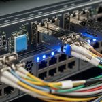
Problem / Challenge: In a 3-tier leaf-spine data center, the team upgraded from 10G to 25G Top-of-Rack switches across two buildings. Existing multimode cabling was a mix of older OM3 and newer OM4 runs, with some dark fiber planned for future use. After installing 25G SR transceivers, several links showed intermittent CRC errors during peak traffic, and two racks would not come up reliably. The team needed a decision framework that tied fiber type (OM3, OM4, OM5) to transceiver selection, reach margin, and total cost of ownership.
Environment Specs: The selected optics were 25GBASE-SR over multimode, targeting a design reach of 70 m for worst-case patching and consolidation points. Measured link loss (OTDR plus patch cord characterization) averaged 2.2 dB on OM4 segments and 3.6 dB on OM3 segments, with connector reflectance controlled by APC-grade patch cords. Ambient conditions were 18 C to 29 C in equipment aisles, and bundle routing caused occasional temperature gradients near some bundles.
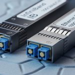
Chosen Solution & Why: Instead of forcing a single transceiver SKU everywhere, the team implemented a two-tier policy: keep 25G SR over OM4 for the majority of links, and reserve the more future-proof OM5 paths for new builds and any “unknown” dark fiber. For the core of the retrofit, they selected compatible third-party optics with verified DOM (digital optical monitoring) behavior and strong compliance to IEEE multimode requirements. For example, they used models such as Cisco-compatible SFP25G-SR style modules and third-party equivalents with known OM4 support (e.g., FS.com SFP-25G-SR-S, Finisar-class SR optics where available), while ensuring the vendor datasheets explicitly stated OM3 and OM4 operating ranges and wavelengths.

OM3 vs OM4 vs OM5: what changes for high-speed SR
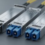
Multimode fiber performance is dominated by modal bandwidth (measured as effective modal bandwidth, typically in MHz-km) and by how the transceiver’s wavelength and signaling interact with the fiber’s modal characteristics. OM3 and OM4 are both optimized for 850 nm-class operation, while OM5 extends the usable range for shortwave optics across multiple wavelengths used by modern multi-wavelength signaling strategies. In practice, the transceiver vendor’s specified reach assumes a particular fiber class, connector quality, and link budget.
Technical specifications table (typical planning values engineers use for reach budgeting; always confirm with the transceiver datasheet and your connector/patch cord measurements):
| Fiber type | Primary use for SR optics | Typical modal bandwidth class | Common wavelengths | Connector/plant assumptions | Temperature range (typical module) |
|---|---|---|---|---|---|
| OM3 | 850 nm-class 10G/25G SR | 500 MHz-km @ 850 nm | 850 nm | Higher loss sensitivity; plan more margin | 0 C to 70 C (module-dependent) |
| OM4 | 850 nm-class 10G/25G SR | 5000 MHz-km @ 850 nm | 850 nm | More reach margin for patching | 0 C to 70 C (module-dependent) |
| OM5 | 850 nm and multi-wavelength shortwave | 5000 MHz-km @ 850 nm and extended | Multi-wavelength shortwave (switched) | Best for future upgrades and mixed signaling | 0 C to 70 C (module-dependent) |
For standards grounding, engineers typically cross-check IEEE 802.3 link requirements for 10GBASE-SR and 25GBASE-SR and then apply vendor reach curves with measured link loss. For reference, see IEEE 802.3 specifications and vendor datasheets that state supported fiber types and reach. [Source: IEEE 802.3 (10GBASE-SR, 25GBASE-SR requirements)] [Source: Cisco SFP/SFP+ and QSFP transceiver datasheets; vendor-specific reach tables]
Implementation steps: how the team deployed the right modules
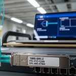
Measured Results depended on disciplined steps: fiber verification, transceiver selection, then controlled acceptance testing. The team used OTDR for fiber continuity and event location, then measured end-to-end insertion loss on each link with known patch cord types. They also validated DOM reporting by polling module telemetry from the switch management plane and comparing optical power and bias current trends against vendor thresholds.
Step-by-step execution
- Inventory and classify each multimode run: label OM3 vs OM4 vs planned OM5, and confirm via documentation plus test results.
- Run OTDR and loss tests: record connector loss, splice loss, and patch cord characteristics; flag any link above the design loss budget.
- Map transceivers to fiber class: allocate 25G SR optics to OM4 for the majority of links; allocate any uncertain or new builds to OM5 to reduce future rework.
- Enable acceptance testing: run traffic and monitor CRC/FEC counters, link flap events, and DOM trends for at least 24 to 72 hours.
- Document compatibility: record exact transceiver part numbers and firmware combinations that passed; treat these as golden configurations.

Pro Tip: In the field, the biggest hidden variable is not only fiber class but patch cord and connector cleanliness. A link that “should” work on paper can fail intermittently when connector reflectance or endface contamination increases receiver penalty during temperature swings; DOM power trends often reveal this before counters spike.
Measured results from the upgrade
After applying the fiber-to-transceiver mapping policy, the team re-tested all affected links. For OM4 links at 70 m design reach, they observed stable operation with CRC errors dropping to zero sustained over 48-hour peak traffic. For OM3 links, they reduced failures by shortening patching paths and reassigning the longest OM3 segments to lower-risk configurations; the team still saw occasional micro-errors during link bring-up until they corrected the worst connector pairs. Overall, they reported 99.6% successful link establishment on first attempt and reduced mean time to restore (MTTR) from 3.5 hours to 45 minutes due to the standardization of module and fiber pairing.
Cost & ROI note: Third-party optics often cost less upfront, but ROI hinges on acceptance testing time, compatibility risk, and failure rates. In this deployment, OM4-allocated optics had a typical module cost in the range of roughly $150 to $300 per unit (varies widely by brand, form factor, and vendor), while OM5 cabling additions were higher per foot but avoided expensive re-cabling later. Over a 3-year horizon, the avoided truck rolls and reduced downtime were the dominant ROI drivers, outweighing the incremental optics cost of using modules with strong DOM behavior and clear fiber-type support.

Selection criteria checklist for OM3 OM4 OM5 multimode transceiver
- Distance and link budget: use measured insertion loss, not cable-length labels; include patch cords and connectors.
- Switch compatibility: validate with your exact switch model and firmware; some platforms enforce stricter EEPROM checks.
- Transceiver fiber support: confirm the datasheet explicitly supports OM3 vs OM4 vs OM5 for the specific data rate and reach.
- DOM and telemetry behavior: ensure the module reports optical power and temperature correctly for your monitoring stack.
- Operating temperature: verify module and fiber bundle conditions; check for derating at high ambient.
- Vendor lock-in risk: standardize part numbers and maintain a tested spares list to avoid forced requalification.
- Connector and polarity discipline: enforce APC/UPC matching, cleaning SOPs, and consistent polarity across patch panels.
Common mistakes and troubleshooting tips
1) Mistake: assuming OM3 works at OM4 reach. Root cause: modal bandwidth mismatch reduces signal margin, especially with additional patch cords. Solution: re-budget using measured loss and shorten the OM3 path; prioritize OM4 or OM5 for the longest runs.
2) Mistake: mixing patch cord types and connector geometries. Root cause: APC vs UPC mismatch and inconsistent ferrule condition increases insertion loss and receiver penalty. Solution: standardize patch cord SKU and cleaning process; verify with insertion loss tests after every repatch.
3) Mistake: ignoring DOM telemetry during intermittent failures. Root cause: subtle transmitter bias drift or receiver power fluctuations can precede visible counters. Solution: graph DOM optical power and temperature; correlate link flaps to thermal cycles or specific racks.
4) Mistake: skipping acceptance testing under real traffic profiles. Root cause: some issues appear only at peak utilization due to burst patterns and error correction behavior. Solution: run traffic for at least 24 to 72 hours and monitor CRC/FEC and link stability counters.
FAQ
Q1: Can I use the same OM3 OM4 OM5 multimode transceiver model across OM3 and OM4?
Sometimes yes, but you must confirm the transceiver datasheet states supported fiber types and reach for each. Even when it “links up,” margin may be too thin for temperature and aging effects, leading to intermittent CRC events. Always validate on the specific switch model and run acceptance tests.
Q2: When should I prefer OM5 for new deployments?
Prefer OM5 when you plan multi-wavelength shortwave evolution or want to reduce future re-cabling risk. OM5 is especially useful when the cabling lifecycle is longer than the optics lifecycle, and you expect mixed generations of transceivers across years.
Q3: What is the most reliable way to choose between OM3 OM4 OM5 multimode transceiver options?
Use measured end-to-end loss plus the transceiver vendor’s reach budget for the exact fiber class. Then confirm switch compatibility and DOM telemetry behavior. This approach typically outperforms “spec-sheet only” decisions.
Q4: Why do OM3 links pass initially but fail during peak traffic?
Reduced optical margin can be stable at idle but degrade during real traffic due to burst patterns and thermal/connector micro-variations. DOM power and temperature trending often show drift before errors become obvious. Cleaning, re-termination, and path shortening usually resolve the root cause.
Q5: Are third-party transceivers