When an offshore platform fiber network starts dropping packets, the culprit is often not the switch, but the optics failing under salt spray, vibration, and temperature swings. This article helps field engineers and network owners select and validate offshore oil rig optics using SFP modules designed for extreme environments. You will get practical selection criteria, a specs comparison table, deployment guidance, and troubleshooting patterns that show up during commissioning and maintenance.
Why offshore oil rig optics stress SFP transceivers differently
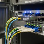
Offshore platforms compress multiple failure drivers into the same rack: conductive salt deposits, cyclic thermal expansion, constant vibration from rotating machinery, and long cable runs in humid, sometimes corrosive air. Even when the optical budget looks healthy on paper, marginal link margins can collapse during a storm-related temperature swing or after a maintenance crew re-terminates fiber. In practice, engineers must treat SFP selection as an end-to-end system problem: optics, fiber type, connector cleanliness, and physical layer validation.
What matters at the physical layer
Most offshore networks use Ethernet over fiber built on IEEE 802.3 PHY behavior and link training. SFPs implement the optical transmitter and receiver plus the electrical front end; they must meet the host switch’s electrical interface requirements and the optical wavelength plan. For multimode links, you also contend with modal distribution and differential mode delay; for single-mode, you contend with connector loss and polarization sensitivity only if you are using coherent optics (rare for SFP in this context).
Environmental requirements that change the decision
In the field, the “spec sheet reach” is less important than the guaranteed operating envelope. Many standard SFPs are rated for commercial temperature ranges and may pass a bench test but drift after months of vibration. Offshore-qualified optics typically target wider temperature ranges, improved mechanical retention, and better tolerance to dust and salt residue. Always verify the vendor’s datasheet for operating temperature, link budget guidance, and whether the module supports DOM (Digital Optical Monitoring).
Pro Tip: In offshore deployments, DOM alarms often arrive before a full link outage. Track DOM thresholds for received power, laser bias current, and temperature in your NMS, then correlate with maintenance logs. This turns “mystery downtime” into a measurable degradation curve you can act on during planned vessel downtime.

Key SFP specs for extreme-environment offshore links
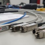
Engineers selecting offshore oil rig optics should start with the data rate and wavelength plan mandated by the switch and cabling. Then, validate the physical layer by matching fiber type to the optical interface: SR for multimode and LR/ER for single-mode are common patterns. Finally, confirm that the module’s power, wavelength, and temperature range stay within the host switch’s tolerance across the year.
Spec comparison: common offshore-appropriate SFP patterns
The table below compares representative SFP module configurations commonly used in marine and offshore-adjacent networks. Actual availability varies by vendor and qualification program, so confirm exact model numbers and environmental ratings on the datasheet.
| Module type | Data rate | Wavelength | Typical reach | Fiber type | Connector | DOM | Operating temperature (target) | Notes for offshore use |
|---|---|---|---|---|---|---|---|---|
| SFP-10G-SR | 10G | ~850 nm | up to 300 m (MMF) | OM3/OM4 | LC | Yes (typically) | -40 to +85 C (verify per model) | More sensitive to connector cleanliness and MMF quality |
| SFP-10G-LR | 10G | ~1310 nm | 10 km (SMF) | OS2 single-mode | LC | Yes (typically) | -40 to +85 C (verify per model) | Best for longer runs across risers and cable trays |
| SFP-1G-LX | 1G | ~1310 nm | up to 10 km | OS2 single-mode | LC | Yes (varies) | -40 to +85 C (verify per model) | Often used for legacy control networks |
For concrete examples, many networks deploy vendor SFPs such as Cisco SFP-10G-SR (when compatible with the host platform), and optics from recognized transceiver vendors like Finisar FTLX8571D3BCL for 10G-SR class links. For third-party sourcing, check module compliance and environmental rating; for instance, some FS.com SFP-10GSR offerings target industrial temperature ranges, but you must verify the exact SKU against your contract requirements.
Authority references: IEEE 802.3 for Ethernet physical layer behavior and link requirements, and vendor datasheets for temperature, DOM, and optical parameters. [Source: IEEE 802.3 standard] [Source: Cisco SFP datasheets] [Source: Finisar/Viavi optical transceiver datasheets] [Source: FS.com transceiver datasheets]

Field deployment scenario: leaf-spine fiber on a 3-tier offshore network
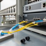
Consider a realistic commissioning in a 3-tier offshore platform data center: 48-port 10G ToR switches at the process-control rooms, aggregation switches in the communications bay, and a core pair in the main rack. The cabling plan uses 10G-SR for short in-bay links over OM4 multimode (about 80 to 150 m each), and 10G-LR for longer runs between bays over OS2 single-mode (about 3 to 8 km via risers and cable trays). During acceptance testing, the team verifies link negotiation at line rate, then performs a DOM snapshot and OTDR pass on each fiber span.
In this environment, engineers typically stock spares in a sealed dry cabinet with desiccant and humidity monitoring. During storm season, they re-check DOM received power every two weeks and after any cabinet door opening. The operational lesson is that offshore oil rig optics must be validated not just for optical power, but for mechanical retention and connector integrity after vibration events.
Selection checklist: how engineers pick SFPs that last
Offshore optics selection is a disciplined process. Use the ordered checklist below during procurement and during pre-deployment verification so you do not discover incompatibilities during a maintenance window.
- Distance and fiber type: confirm whether the link is MMF (OM3/OM4) or SMF (OS2). Match SR vs LR/ER class optics accordingly.
- Switch compatibility: verify the host switch supports the exact SFP type and speed. Some platforms are sensitive to transceiver vendor EEPROM behavior and DOM format.
- Optical budget: calculate worst-case receive power with connector loss, splice loss, aging margin, and safety margin. Validate using vendor guidance and your measured link losses.
- DOM support and monitoring thresholds: choose modules with DOM that your NMS can read. Ensure you can alert on low received power and temperature excursions.
- Operating temperature and qualification: confirm the module’s guaranteed temperature range and any vibration or shock qualification claims.
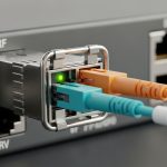
- Connector and cleaning plan: confirm LC/APC vs UPC behavior where relevant, and align with your cleaning tools and procedures. Offshore dust and salt residue are real loss drivers.
- Vendor lock-in risk: if the platform only accepts certain transceiver IDs, negotiate spares and qualification terms up front. For third-party optics, require proof of compatibility and environmental rating.

Common pitfalls and troubleshooting patterns
Even careful teams run into recurring offshore failure modes. Below are concrete mistakes engineers make, the likely root cause, and what to do next.
Pitfall 1: “Link works on the bench, fails offshore” after vibration
Root cause: the module passes initial optical power checks but has marginal mechanical retention or connector seating. Vibration loosens a patch-cord, causing intermittent high loss. Solution: verify the module is fully latched, use vibration-rated patch panels and strain relief, and re-check optical power after any cabinet movement. Add DOM-based alerts for received power dips to catch intermittent loss early.
Pitfall 2: Mis-matched fiber type leading to weak receive power
Root cause: an SR optics module is installed on a link actually terminated for single-mode, or OM3 is treated as OM4 without validation. Modal mismatch and incorrect attenuation characteristics cause lower-than-expected receive power and higher error rates. Solution: confirm fiber type labeling, run a fiber certification test where possible, and measure link loss end-to-end before swapping optics.
Pitfall 3: Over-aggressive cleaning schedules or wrong connector handling
Root cause: using incompatible wipes, reusing dirty cleaning tips, or skipping inspection under magnification. Salt residue can smear into the ferrule and create a permanent film that increases loss over time. Solution: use approved fiber inspection microscopes, follow manufacturer cleaning guidance, and implement a “clean then inspect” workflow. After cleaning, re-run receive power and, if available, OTDR checks.
Pitfall 4: DOM alarms ignored because thresholds are not tuned
Root cause: default thresholds trigger too many false positives, so operators silence alarms and miss the real degradation signal. Solution: baseline DOM readings during commissioning, then set thresholds based on measured variance and your expected environmental drift. Document the correlation between temperature and received power so you can differentiate normal drift from true link degradation.
Cost and ROI: what offshore buyers actually weigh
Pricing varies widely by data rate, wavelength, and qualification requirements. As a realistic planning number, standard 1G or 10G SFPs may range from roughly tens to a few hundred USD per module in bulk, while ruggedized or industrial-grade versions can cost more, particularly when they include expanded temperature guarantees and tighter quality controls. OEM optics can carry a premium due to host compatibility promises, while third-party optics can reduce unit cost but may increase spares complexity if the platform enforces strict transceiver ID behavior.
TCO is driven by downtime cost and logistics constraints. A single failed link during a critical operation can trigger boat scheduling, technician travel, and extended testing windows. The ROI case improves when you reduce mean time to repair by stocking the right spares, enabling DOM-based predictive maintenance, and standardizing on optics families with stable compatibility. In other words: offshore oil rig optics buys reliability, not just optical reach.
FAQ
What fiber type is most common for offshore oil rig optics?
Short in-bay runs frequently use multimode fiber with OM3 or OM4 for SR optics because distances are modest and installation is straightforward. Longer risers and cross-bay paths often use single-mode OS2 with LR-class optics to reduce attenuation and improve reach.
Do I need DOM support for offshore monitoring?
DOM is strongly recommended. With it, you can monitor received power, laser bias current, and module temperature, which helps you detect degradation before a full outage. Some operators integrate DOM telemetry into their NMS and set alert thresholds based on commissioning baselines.
How do I verify compatibility with my switch model?
Check the switch vendor’s transceiver compatibility list or supported optics guidance, then validate in a controlled staging environment. Pay attention to EEPROM and DOM formatting expectations; some hosts are sensitive to transceiver identification behavior even when optical specs look correct.
What are the most likely causes of intermittent link flaps offshore?
Common causes include connector contamination after maintenance, patch-cord movement due to vibration, and mis-terminated fiber or incorrect fiber type. DOM plus packet counters can help separate optical power issues from host-level negotiation or cabling faults.
Are third-party SFPs safe for offshore use?
They can be safe if you require evidence of compatibility and confirm the exact environmental operating range for your SKU. Ask for datasheets, test reports, and a clear warranty path, and then run a soak test in a staging rack that mimics your temperature and power conditions.
How should we plan spares inventory?
Start with the number of active links, then add spares based on your maintenance strategy and lead times. If offshore logistics are slow, stock enough optics to swap quickly and verify with DOM readings and measured receive power to avoid extended troubleshooting on limited access windows.
Offshore oil rig optics selection is won or lost by environmental fit, compatibility discipline, and field validation—not just by reach numbers. If you want to go one step further, review fiber transceiver commissioning workflow to standardize how you test, baseline DOM, and certify links before operations.
Author bio: I have deployed fiber access and aggregation links on constrained industrial sites, including staged commissioning with DOM telemetry baselines and OTDR verification. My work focuses on turning optical budgets into operational reliability under vibration, humidity, and maintenance-driven change.