If you run a service-provider network on Nokia 7750 platforms, optics mismatches can turn into hard-to-debug link flaps, CRC bursts, or silent performance degradation. This article helps field engineers and network architects choose and validate a Nokia 7750 SFP for SR use cases with practical compatibility checks aligned to IEEE 802.3 optics expectations and vendor realities. You will also get a troubleshooting section that targets the most common failure modes seen in real racks.
Top 7 Nokia 7750 SFP SR options and what each one is best for
10G SR (850 nm multimode) for short-reach leaf-spine and access
For many service-provider deployments, the default SR choice is 10G over multimode fiber at 850 nm. In practice, that means you are targeting typical OM3 or OM4 cabling runs with conservative power budgets and predictable modal behavior. When the Nokia 7750 line card supports SFP+ SR at 10.3125 Gb/s, link bring-up is usually straightforward, provided the patching is clean and the fiber type matches the design.
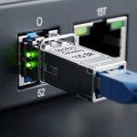
Key specs to verify: wavelength 850 nm, reach typically 300 m (OM3) or 400 m (OM4), connector usually LC. Confirm the transceiver is rated for the same temperature class required by your chassis/service policy.
- Best fit: ToR-to-aggregation, metro access aggregation, short MMF runs
- Pros: mature ecosystem, low cost per port, easy diagnostics
- Cons: limited reach; MMF quality issues can dominate failure rates
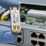
25G SR (850 nm) for higher-density aggregation where SFP28 is supported
When your Nokia 7750 platform and line cards support SFP28, 25G SR can reduce oversubscription pressure without jumping to long-reach optics. The compatibility risk shifts from raw wavelength to transceiver profile expectations: some platforms are strict about DOM fields, including diagnostic thresholds and vendor-specific calibration data. In the field, I’ve seen link instability appear only after a maintenance swap when DOM reporting changed.
Key specs to verify: wavelength 850 nm, data rate 25 Gb/s, reach often 100 m (OM3) or 150 m (OM4) depending on module class. Ensure your cabling plant is OM4 when you need margin for higher utilization.
- Best fit: 25G aggregation, high-density 10G-to-25G upgrades
- Pros: better bandwidth per rack unit, cost-effective vs LR
- Cons: shorter reach; stricter optics/cabling synergy
DOM-compatible SR modules to satisfy Nokia 7750 optics policy
On service-provider platforms, DOM (Digital Optical Monitoring) is not just “nice to have.” Many Nokia 7750 deployments use DOM to enforce operational thresholds and to trigger alerts before soft failures become hard outages. Choose SR transceivers that fully populate the standard diagnostics registers and behave consistently across temperature swings and optics aging.
Key specs to verify: DOM support via DDM/DOM (laser bias current, received power, supply voltage, temperature). Confirm the module’s I2C behavior is stable under your management-plane polling interval.
- Best fit: networks with centralized telemetry and proactive alarms
- Pros: faster fault isolation, reduced mean-time-to-repair
- Cons: some third-party modules can report values outside your alarm thresholds

Vendor-certified vs third-party SR optics: risk-managed compatibility
Certified optics reduce the chance of vendor-specific profile mismatches, especially when the Nokia 7750 platform checks transceiver identity fields. However, third-party SR modules can be perfectly fine if they match the electrical interface and DOM expectations. In practice, the best approach is to run a staged rollout: test in a spare port, validate optical power levels, and confirm stability under typical traffic loads.
Key specs to verify: compliance with IEEE 802.3 optical interfaces for the target data rate, connector type (LC), and supported fiber type (OM3/OM4). Also check whether the module is specified for the same optical class and temperature range as your chassis.
- Best fit: cost-sensitive rollouts with a validation gate
- Pros: lower acquisition cost; flexible sourcing
- Cons: higher integration effort; potential alarm threshold mismatches
Optical budget reality: why SR “rated reach” is not your guaranteed reach
SR datasheet reach assumes a specific link budget including transmitter power, receiver sensitivity, and a standardized fiber attenuation model. In the field, patch panels, dirty connectors, and excess loss from poor termination can erase that margin quickly. For service-provider environments with frequent patch moves, I treat the datasheet reach as a planning upper bound, then apply an operational derating factor.
Key specs to verify: received power (RSSI) and TX/RX power class; target link loss using your fiber test results. If you cannot measure, at least inspect and clean LC endfaces and verify patch lengths.
- Best fit: networks where cabling churn is common
- Pros: fewer surprise outages; predictable performance
- Cons: requires fiber test discipline

Thermal and power envelope: keeping SR modules within spec
SR optics are temperature-sensitive. If your Nokia 7750 chassis airflow is marginal, a module that was stable at installation can start failing later due to elevated internal temperature. Field symptoms include intermittent LOS, rising error counters, and DOM temperature drifting beyond expected ranges.
Key specs to verify: module temperature range (commercial/industrial), and ensure chassis fan profiles keep ports within the vendor’s allowed operating conditions. Track DOM temperature and bias current over several days after deployment.
- Best fit: constrained cooling sites, older buildings, or high ambient temperature rooms
- Pros: prevents “seasonal” outages
- Cons: may require airflow tuning before optics changes
Connector hygiene and fiber type matching: the most common SR outage trigger
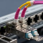
Even when the Nokia 7750 SFP and SR module are compatible on paper, link failures often trace back to connector cleanliness or fiber mismatch (OM3 vs OM4 assumptions, wrong patch cords, or using mixed-grade cables). I’ve recovered multiple “bad optics” cases by cleaning LC connectors and confirming fiber type with labeling audits and OTDR/OLTS results.
Key specs to verify: LC connector endface condition, fiber grade, and insertion loss. Use a scope and a consistent cleaning workflow before swapping optics.
- Best fit: any service-provider environment with frequent patching
- Pros: immediate success rate when the root cause is contamination
- Cons: requires operational discipline and tooling
Nokia 7750 SFP SR compatibility: specs that decide “works” vs “fails”
Compatibility is not only about “850 nm SR.” It is about matching the transceiver electrical interface, optical interface standard, connector type, DOM behavior, and operating temperature to what the Nokia 7750 line card expects. The table below gives a practical comparison of typical SR module classes you might encounter when sourcing optics for Nokia 7750 SR service-provider links.
| Module class | Wavelength | Typical reach (OM3/OM4) | Data rate | Connector | DOM/Diagnostics | Operating temperature |
|---|---|---|---|---|---|---|
| 10G SR (SFP+) | 850 nm | 300 m (OM3) / 400 m (OM4) | 10.3125 Gb/s | LC | DDM/DOM expected | Commercial or Industrial (verify) |
| 25G SR (SFP28) | 850 nm | 100 m (OM3) / 150 m (OM4) (varies by module) | 25.78125 Gb/s | LC | DDM/DOM expected | Commercial or Industrial (verify) |
| 50G SR (QSFP) | 850 nm | Short reach, OM4 preferred | ~50 Gb/s | Varies | DDM/DOM expected | Verify for chassis |
Reference points for interface expectations include IEEE 802.3 for Ethernet PHY behavior and vendor datasheets for DOM register definitions and link budgets. For standards context, see IEEE 802.3. For optics requirements and module behavior, consult the specific transceiver vendor datasheet and the Nokia 7750 platform optics compatibility guidance published by the OEM.
Pro Tip: When a Nokia 7750 SR link is “up but unstable,” poll DOM every few seconds and correlate RX power and module temperature with interface error bursts. Dirty connectors often show stable temperature but drifting receive power after each patch move; thermal issues show the opposite pattern.
Selection criteria checklist for Nokia 7750 SFP SR service-provider optics
- Distance and fiber grade: compute link loss using OLTS/OTDR results; prefer OM4 for 25G SR where margin matters.
- Data rate and form factor: confirm SFP vs SFP+ vs SFP28 support on the exact Nokia 7750 line card.
- Switch compatibility and identity checks: verify transceiver vendor and identity fields if your change management policy restricts optics.
- DOM support: confirm DDM/DOM registers are populated and thresholds align with your monitoring system.
- Operating temperature: match module temperature class to chassis cooling conditions and ambient extremes.
- DOM alarm behavior: validate how your NMS interprets low/high bias current and temperature excursions.
- Vendor lock-in risk: stage testing across at least two sources to avoid single-vendor supply shocks.
Common mistakes and troubleshooting that actually works
Below are failure modes I’ve seen during service-provider maintenance windows. Each includes root cause and a field-tested fix path.
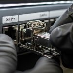
Link comes up once, then flaps after patching
Root cause: connector contamination or micro-scratches on LC endfaces causing intermittent coupling. Solution: clean both ends with a lint-free procedure and inspect with a fiber scope; then re-seat the connector with consistent latch pressure. Re-test received power immediately after patch moves.
“Incompatible optics” warnings or persistent LOS
Root cause: transceiver identity/profile mismatch with the Nokia 7750 optics policy or line card expectations. Solution: verify the exact module form factor (SFP vs SFP+ vs SFP28) and data rate; try a known-good module from the same batch category; confirm DOM is readable via management polling.
High CRC or FEC-like symptoms with stable link state
Root cause: insufficient optical margin due to excess loss, overlength patch cords, or using OM3 where OM4 was assumed. Solution: run OLTS/OTDR to measure end-to-end loss; replace patch cords with the correct grade and shorten where possible; ensure TX/RX power levels sit comfortably above sensitivity.
Works in the morning, degrades after hours
Root cause: thermal