If your enterprise network has intermittent packet loss, link flaps, or unexplained latency spikes, the optical switch is often the hidden culprit. This article helps network engineers and reliability folks select the right optical switch for enterprise-grade network reliability, with practical checks tied to real transceivers and fiber plant conditions. You will get a spec comparison table, a decision checklist, and field-tested troubleshooting patterns.
What an optical switch must do for network reliability
Optical switches route traffic across optical paths, and their reliability depends on stable optical power, predictable switching behavior, and tight environmental control. In practice, you are validating end-to-end link stability: the optical switch must work cleanly with your transceivers (SFP/SFP+/QSFP28/CXP), your patch panels, and your fiber type (OM3, OM4, OS2). The IEEE 802.3 PHY runs the show at Layer 1/2, but the switch optics influence whether the PHY ever sees a stable signal.
For measurable reliability, vendors often publish MTBF, insertion loss, optical power budgets, and operating temperature ranges. You should also look for telemetry features (for example, real-time temperature and optical power alarms) because “silent failures” are common when optics drift slowly. [Source: IEEE 802.3 Ethernet Standards Overview] [[EXT:https://standards.ieee.org/standard/]]

Key specs to verify before you buy
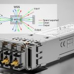
Optical switches come in different architectures (MEMS, thermo-optic, or other approaches) and with different optical characteristics. Your job is to ensure the switch’s insertion loss and switching performance fit your optical budget and that the transceiver wavelengths align with the rest of the link. Don’t treat this as a generic compatibility exercise; validate with actual module part numbers used in your network.
Specs that matter in real deployments
Engineers typically sanity-check: wavelength compatibility, channel count, insertion loss, maximum optical power, and connector type. They also check operating temperature and whether the switch supports DOM signaling pass-through for optics monitoring. If DOM is not supported end-to-end, you may lose early warning alarms that prevent outages.
| Spec | What to check | Why it impacts network reliability |
|---|---|---|
| Wavelength support | 850 nm (SR), 1310/1550 nm (LR/ER/ZR) | Mismatch can cause receiver underflow and link flaps |
| Insertion loss (dB) | Switch IL plus patch cords and splitters | Reduces optical power margin for the receiver |
| Optical power handling | Max input and safe output power | Over-power can degrade optics and increase BER |
| Connector type | LC/SC, APC vs UPC (where relevant) | Bad polish or wrong mating style raises back-reflections |
| Data rate / PHY compatibility | 10G/25G/40G/100G optics support | Some switches behave differently under higher symbol rates |
| Operating temperature | Typical and max ambient in the rack | Thermal drift affects optical alignment and switching stability |
| Telemetry and alarms | Temperature, power, port status | Improves MTTR by catching drift before failure |
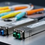
Transceiver examples you should cross-check
Even if the optical switch is “compatible with fiber,” your actual optics matter. Common enterprise optics include Cisco SFP-10G-SR, Finisar FTLX8571D3BCL, and FS.com SFP-10GSR-85. Validate the wavelength (for example, SR at 850 nm), reach (OM3 vs OM4), and receiver sensitivity in the vendor datasheet, then add switch insertion loss into the budget. [Source: Vendor transceiver datasheets for Cisco, Finisar, and FS.com]
Pro Tip: In field audits, the biggest reliability wins usually come from verifying the optical power margin after the switch, not just whether the wavelength matches. A switch with “acceptable” insertion loss on paper can still fail in your rack if patch cords are long, connectors are dirty, or you have extra inline splitters.
Decision checklist: selecting an optical switch for enterprise reliability
Use this ordered list the way QA and reliability teams actually work: start with physics (budget and wavelength), then move to operational behavior (telemetry and alarms), then finish with lifecycle risk (support and spares).
- Distance and optical budget: compute end-to-end loss including switch insertion loss, patch cord loss, and any splitters; confirm receiver sensitivity margin at your expected ambient temperature.
- Wavelength and fiber type: ensure the switch path supports your optics (SR 850 nm vs LR/ER/ZR bands) and your plant is OM3/OM4/OS2 as expected.
- Switch insertion loss and power handling: verify maximum input/output power limits and confirm the IL spec under realistic operating conditions.
- Switch control and failure mode: check how the switch behaves during reboot, link loss, or control-plane disruption; confirm deterministic restoration.
- DOM and monitoring strategy: confirm whether transceiver diagnostics remain visible to your monitoring stack end-to-end.
- Operating temperature and airflow: compare vendor specs to your rack’s measured inlet temperature; plan for worst-case summer peaks.
- Switch compatibility with your optics: test with the exact transceiver models you already standardize on.
- Vendor lock-in and spares: assess warranty terms, lead times, and the cost of replacing failed units; check availability of compatible modules.

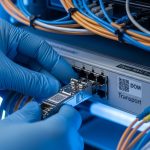
Real-world deployment scenario: where reliability breaks
In a 3-tier data center leaf-spine topology with 48-port 10G ToR switches per rack and two uplinks per server block, the team replaced a legacy optical cross-connect with a new optical switch to increase path flexibility. Each rack used OM4 trunks with SR optics and short patch cords, but the new switch had higher insertion loss than the old unit. Over three weeks, alarms showed rising receive error counts during peak afternoon HVAC cycles; the inlet temperature rose from 24 C to 30 C, and optical alignment drift reduced receiver margin. After revalidating the optical budget and swapping to shorter patch cords and cleaner connector polish, link flaps dropped to near zero and MTTR improved because telemetry started reporting temperature and path state changes earlier.

Common mistakes and troubleshooting tips
These are the failure patterns that show up repeatedly in reliability reviews, along with root causes and practical fixes.
“Wavelength matches, so it should work” (it doesn’t)
Root cause: SR 850 nm optics used with a switch path intended for 1310/1550 nm, or mixed optics across lanes. Solution: verify wavelength bands on both sides, then standardize transceiver part numbers; run a controlled link test at install time.
Link flaps after adding the switch
Root cause: optical budget went negative due to switch insertion loss plus long patch cords or extra connector pairs. Solution: recalculate budget using measured patch cord lengths; clean connectors, confirm APC/UPC mating where applicable, and reduce loss.
Telemetry gaps hide early warning signs
Root cause: DOM/diagnostics not forwarded or not polled by your management system, so you only notice failures when BER spikes. Solution: confirm monitoring visibility for temperature, supply voltage, and optical power; align alarms with your NOC thresholds.
Thermal drift in dense racks
Root cause: switch operating temperature is within spec, but rack inlet temperature is near the max, causing slow drift and higher error rates. Solution: measure inlet temps over a full day; improve airflow and consider relocating the switch or adjusting fan profiles.
Cost and ROI: what you should budget realistically
Optical switches vary widely, but in many enterprise deployments you might see hardware spend ranging from mid five figures for smaller channel-count units to six figures for higher-capacity platforms, plus installation labor. OEM optics and vendor-certified transceivers often cost more than third-party equivalents, but they reduce compatibility surprises. A practical TCO model includes: power draw, spares holding costs, warranty coverage, and downtime cost; reliability improvements that cut MTTR and prevent repeat field replacements can outweigh higher upfront module pricing.
If budget pressure pushes you toward third-party optics, require vendor interoperability testing with your exact switch model and your standardized transceiver list. The ROI case strengthens when you treat optical budget validation and telemetry alignment as part of the acceptance test, not as an afterthought.
FAQ
How does an optical switch affect network reliability compared to cabling?
It affects reliability by adding insertion loss, introducing optical path variability, and influencing how quickly you detect drift via telemetry. Cabling issues mainly show up as connector loss or contamination, while a switch can create systematic margin reduction across many links.
Should I prioritize MTBF figures or optical budget validation?
Both matter, but optical budget validation is usually the faster path to immediate risk reduction. MTBF is helpful for lifecycle planning, yet many real outages come from margin loss, thermal drift, or monitoring gaps that MTBF cannot predict.
Do I need DOM support for enterprise-grade monitoring?
Yes, if your reliability program depends on early warning alarms. Without DOM visibility, you may miss rising temperature or optical power degradation until the link fails, increasing MTTR.
What fiber types are most sensitive when using optical switches?
Short-reach multimode designs are sensitive to patch cord loss and connector cleanliness, especially with SR optics on OM3/OM4. Single-mode OS2 setups tend to be more tolerant of certain loss variations, but they still require correct wavelength planning.
What acceptance tests should I run before rollout?
Run wavelength compatibility checks, verify optical power margin with your exact transceiver models, and stress the system under your worst-case ambient temperatures. Also confirm alarm propagation into your NOC tooling so you can respond before BER causes visible outage.
Are third-party transceivers safe with optical switches?
They can be, but only after compatibility testing with the specific switch and your standardized optics. Differences in vendor implementation can affect DOM behavior, timing, or optics calibration, which impacts reliability.
.wpacs-related{margin:2.5em 0 1em;padding:0;border-top:2px solid #e5e7eb} .wpacs-related h3{margin:.8em 0 .6em;font-size:1em;font-weight:700;color:#374151;text-transform:uppercase;letter-spacing:.06em} .wpacs-related-grid{display:grid;grid-template-columns:repeat(auto-fill,minmax(200px,1fr));gap:1rem;margin:0} .wpacs-related-card{display:flex;flex-direction:column;background:#f9fafb;border:1px solid #e5e7eb;border-radius:6px;overflow:hidden;text-decoration:none;color:inherit;transition:box-shadow .15s} .wpacs-related-card:hover{box-shadow:0 2px 12px rgba(0,0,0,.1);text-decoration:none} .wpacs-related-card-img{width:100%;height:110px;object-fit:cover;background:#e5e7eb} .wpacs-related-card-img-placeholder{width:100%;height:110px;background:linear-gradient(135deg,#e5e7eb 0%,#d1d5db 100%);display:flex;align-items:center;justify-content:center;color:#9ca3af;font-size:2em} .wpacs-related-card-title{padding:.6em .75em .75em;font-size:.82em;font-weight:600;line-height:1.35;color:#1f2937} @media(max-width:480px){.wpacs-related-grid{grid-template-columns:1fr 1fr}}