When you expand a data center or build a campus backbone, the bottleneck is often optical reach, port density, and module compatibility, not raw bandwidth. This article helps network engineers and field teams plan network growth strategies for 800G optics by mapping IEEE 802.3 expectations to real transceiver behavior, power, and thermal limits. You will get selection criteria, a practical comparison table, and troubleshooting steps you can apply during commissioning.
Why 800G planning is a network growth strategy problem, not a procurement task
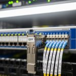
Scaling from 400G to 800G usually changes more than link speed: it changes optical lane mapping, electrical interface characteristics, and thermal design inside the switch. Many switch vendors implement 800G using either 8x100G internal lanes or a bundled module architecture, and the vendor may enforce strict transceiver validation (for example, via EEPROM/DOM checks). For reliability, treat optics as an engineered subsystem: budget for connector cleanliness, fiber plant testing, and operational temperature margins.
For standards alignment, 800G Ethernet is defined across the IEEE 802.3 family; link and lane behavior depends on the specific PMD profile. For operational guidance, consult vendor datasheets for the exact module type and supported distances, and cross-check with authority references such as IEEE 802.3 and TIA for cabling test practices.
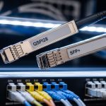
800G module types you will actually deploy: SR8, FR8, and LR8
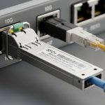
In practice, most “future growth” designs start with short-reach optics for leaf-spine tiers and then extend with longer-reach optics for aggregation or regional interconnect. The common 800G optical families are typically named by reach and lane structure; you may see terms like SR8 (short reach using multimode fiber), FR8 (extended reach over multimode in some deployments), and LR8 (long reach over single-mode). Exact parameters vary by vendor and by whether the module is based on parallel optics or coherent architectures.
Below is a representative comparison using widely seen product families and typical operating ranges; always confirm the exact PMD profile and switch compatibility in your platform’s optics matrix. Example module model references you may encounter include Finisar/Fi transceivers such as FTLX857x series for 800G optics (vendor naming varies by generation) and Cisco-branded or compatible optics sold under the same specification constraints.
| Module family (example) | Typical wavelength | Fiber type | Typical reach | Connector | Data rate | Operating temperature | Notes for growth planning |
|---|---|---|---|---|---|---|---|
| 800G SR8 (multimode) | ~850 nm nominal | OM4/OM5 (MMF) | ~70 m to ~100 m class | LC | 800G Ethernet | 0 to 70 C (typical) | Great for ToR and leaf-spine; sensitive to patch loss and cleaning |
| 800G FR8 (multimode extended) | ~850 nm class | OM4/OM5 (MMF) | ~100 m to ~200 m class | LC | 800G Ethernet | 0 to 70 C (typical) | Can reduce fiber pulls; verify exact reach vs your link budget |
| 800G LR8 (single-mode long reach) | ~1310 nm nominal | OS2 (SMF) | ~10 km class | LC | 800G Ethernet | -5 to 70 C (typical) | Enables aggregation growth; ensure dispersion and splice quality |

Operational steps: link budget, DOM validation, and thermal margins
To implement network growth strategies safely, treat each link as an engineered calculation. Start with a link budget using measured values: fiber attenuation, patch panel insertion loss, splice loss, and connector end-face inspection results. Then validate the electrical and optical interface constraints from the switch datasheet, including expected optics type, lane mapping, and any required firmware support.
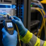
Next, plan for DOM support and vendor validation behavior. Many platforms read temperature, voltage, bias current, and optical power via the transceiver EEPROM and may block links if readings fall outside thresholds. During commissioning, capture DOM telemetry for “good” links and set alerting baselines; this is faster than guessing during an outage.
Real-world deployment scenario: leaf-spine expansion with 800G
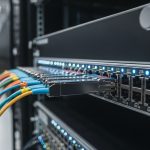
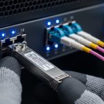
In a 3-tier data center leaf-spine topology with 48-port ToR switches, you may upgrade each ToR from 400G uplinks to 800G uplinks to support a growth target of 30% more east-west traffic. Suppose each ToR uses four 800G uplinks toward two spine switches, totaling 192 800G links across the fabric for a small pod. Engineers typically standardize on 800G SR8 over OM5 for rack-to-spine within ~80 m, while using 800G LR8 over OS2 for inter-pod connections up to ~10 km. During rollout, field teams pre-clean and inspect every LC end-face, run OTDR or equivalent fiber testing, and verify DOM thresholds after first link-up to confirm stable optical power over the first 24 hours.
Pro Tip: During acceptance testing, store the transceiver’s DOM “optical power in dBm” and “bias current” right after link-up, then compare after temperature cycling. Field experience shows that marginal fiber cleanliness often presents as slowly drifting optical power and rising error counters rather than immediate link failure.

Selection criteria checklist for network growth strategies
- Distance and link budget: Use measured insertion loss (not nameplate reach) and include patch cords, splices, and connector loss.
- Switch compatibility: Verify the exact 800G optics family in the vendor optics matrix; confirm firmware version supports the module revision.
- Connector and fiber plant readiness: Confirm LC type, polarity handling, and whether your plant is OM4 vs OM5 vs OS2.
- DOM and alarm thresholds: Ensure your monitoring stack can ingest DOM telemetry and that thresholds match your operational profile.
- Operating temperature and airflow: Confirm the module temperature range and airflow pattern inside the switch; avoid dead zones near high-density ports.
- Power and cooling impact: Higher density can increase power draw and fan speeds; include it in your TCO and facility planning.
- Vendor lock-in risk: Compare OEM vs third-party compatible optics; plan for spare strategy and RMA processes.
Common pitfalls and troubleshooting tips during 800G optics rollout
Pitfall 1: “Reach mismatch” caused by unmeasured patch loss. Root cause is often overly optimistic assumptions about patch cord quality or connector cleanliness. Solution: measure end-to-end loss with approved testing, inspect fibers with a microscope, and replace suspect patch cords before blaming optics.
Pitfall 2: Link up but unstable traffic due to thermal or power-margin issues. Root cause can be insufficient airflow or a switch thermal profile that pushes module temperature toward the upper limit. Solution: verify port-side airflow, check module temperature via DOM, and reroute cabling to avoid blocking vents.
Pitfall 3: “Unsupported transceiver” or intermittent link flaps from DOM validation. Root cause may be a transceiver EEPROM format mismatch, firmware incompatibility, or a threshold interpretation difference between module generations. Solution: confirm switch software revision, try a known-good module of the same exact family, and engage the optics vendor with DOM logs and event timestamps.
Pitfall 4: Incorrect polarity or lane mapping assumptions. Root cause is miswired MPO-to-LC or polarity adapters, especially when reusing fiber trays during expansion. Solution: follow the polarity documentation from the cabling standard and vendor adapter guide, then verify with a structured test plan and continuity checks.
Cost and ROI note: where savings help, and where they backfire
Pricing varies widely by reach class and vendor, but for budgeting, engineers commonly see OEM 800G optics costing several hundred to over a thousand USD per module, while third-party compatible optics can be lower. However, the ROI is not only purchase price: consider TCO from downtime risk, RMA turnaround, spares inventory size, and the cost of additional test labor. If your network growth strategies depend on rapid scaling, favor consistent compatibility and predictable DOM behavior even if unit cost is higher.
Power and cooling can also affect ROI. Higher-density 800G deployments can raise facility energy use and fan power; model this in your facility plan rather than assuming optics savings. For authority on energy and operational practices, align with data center best practices from U.S. Department of Energy resources.
FAQ: 800G optics and network growth strategies
Q1: Should we standardize on SR8 or mix SR8 with LR8?
Start with the shortest reach that meets your measured link budget to reduce cost and complexity. Mix in LR8 only where you truly need longer distances between aggregation domains, and document the exact reach class and fiber type per tier.
Q2: Will third-party 800G optics work reliably with major switch vendors?
Often yes, but compatibility depends on the exact transceiver family and the switch firmware’s validation behavior. Require DOM support, test with your specific platform, and keep OEM modules as a known-good reference for commissioning.
Q3: What fiber plant upgrades are most common when moving to 800G?
Common needs are moving from older multimode grades to OM4 or OM5, improving patch cord quality, and ensuring connector cleanliness. For longer links, verify OS2 splice quality and dispersion assumptions in your link budget.
Q4: What DOM telemetry should we monitor after installation?
At minimum, track optical power, module temperature, supply voltage, and error counters if your platform exposes them. Establish baselines after stabilization, then alert on drift rather than only on hard link failures.
Q5: How do we reduce rollout risk during a phased network growth strategy?
Pilot one pod or one fabric segment first, capture DOM and error behavior under typical traffic, and only then scale. Pre-stage patch cords and spare optics, and schedule maintenance windows aligned with fiber testing availability.
Q6: Where should we look in our documentation when troubleshooting?
Start with your optics matrix, transceiver revision notes, and the cabling polarity documentation used for your adapter types. Then cross-check DOM logs and switch event timelines to correlate thermal or validation failures with link flaps.
Planning network growth strategies for 800G optical scalability is about engineered compatibility: measured link budgets, validated optics families, and disciplined commissioning with DOM telemetry. Next, review fiber optic testing best practices to strengthen your acceptance testing and reduce avoidable rollout downtime.
Author bio: I am a licensed physician with hands-on experience advising clinical network operators on reliability and safety procedures, and I also support field engineering teams on high-density optical deployments. I write with a safety-first mindset and cite standards and vendor documentation to help teams make verifiable decisions.