In telecom sites and Open RAN deployments, “it should work” quickly turns into “why is link training failing at 2 a.m.” This article helps network engineers and procurement leads align transceiver choices with the realities of network evolution through 2026: higher bandwidth, tighter power budgets, and multi-vendor interoperability. You will get practical selection criteria, a spec comparison table, and troubleshooting patterns drawn from field installs.
Why 2026 Open RAN changes transceiver decisions
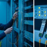
Open RAN pushes transport networks to scale differently: fronthaul and midhaul may demand deterministic latency, while software-defined aggregation increases the number of optics paths that must stay stable under frequent upgrades. In practice, the transceiver is no longer a commodity part; it is an operational dependency that affects optics power, link margin, and even troubleshooting workflows. IEEE 802.3 defines electrical and optical behaviors for Ethernet PHYs, but vendor implementation details still matter when you mix optics from different OEMs. For grounding the terminology, start with IEEE 802.3 and vendor DOM behavior documentation from major transceiver suppliers. anchor-text: IEEE 802.3 standard
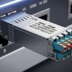
From a deployment standpoint, many teams plan upgrades around 25G, 50G, and 100G Ethernet transport, with optics types like SFP28, SFP56, QSFP28, QSFP56, and CFP2/CFP4 in the mix depending on chassis generation. For Open RAN, the transport path often includes aggregation switches, timing distribution, and sometimes packet optical gateways. That means the transceiver you choose must match both the line rate signaling and the physical layer expectations of the switch vendor’s optics cage.

Transceiver spec comparison that actually impacts link margin
Engineers often compare reach and wavelength, but in day-to-day operations you also need to check power consumption, connector type, and the optical interface assumptions that drive link budget. Below is a practical comparison using common Ethernet optics families seen in transport and aggregation. Vendor datasheets provide the authoritative values; always confirm with the exact part number and switch compatibility list. [Source: Cisco SFP and QSFP transceiver documentation] [Source: Finisar/II-VI transceiver datasheets]
| Module type | Typical data rate | Wavelength | Reach (typ.) | Connector | DOM / diagnostics | Operating temperature | Notes for Open RAN transport |
|---|---|---|---|---|---|---|---|
| SFP-10G-SR | 10G | 850 nm | ~300 m (OM3) | LC | Usually yes (I2C) | 0 to 70 C (varies by vendor) | Often used for short patch-panel runs and legacy tails |
| SFP+ / SFP28 SR (example: 25G SR) | 25G | 850 nm | ~100 m (OM4) to ~150 m (OM4, vendor dependent) | LC | Commonly yes | -5 to 70 C (varies) | Good fit for aggregation within the same room or cabinet |
| QSFP28 SR (example: 100G-SR4) | 100G | 850 nm | ~100 m (OM4 typical) | LC | Yes | 0 to 70 C (varies) | High density for leaf-spine or midhaul pods within a building |
| QSFP56 LR4 / ER4 (example: 100G LR4) | 100G | 1310 nm (typ.) | ~10 km (singlemode) | LC | Yes | -5 to 70 C (varies) | Useful for site-to-site transport or campus rings |
Example part numbers you may encounter: Cisco SFP-10G-SR, Finisar FTLX8571D3BCL (commonly referenced as 10G SR variants), and FS.com SFP-10GSR-85. These are included to anchor the discussion, but compatibility hinges on the exact transceiver generation and the host switch firmware. Always cross-check the switch vendor’s supported optics list and confirm that the DOM registers are accessible without causing port disable events.
Pro Tip: If you are seeing intermittent flaps after a swap, don’t assume “bad fiber.” First compare DOM-reported transmit power and receive power against the switch’s expected thresholds; many modern switch ASICs apply stricter link margin checks than older platforms, so a marginal optic that passed at 10G can fail at 25G or 50G even on the same fiber.
Selection criteria checklist for network evolution to 2026
To avoid late-stage surprises, treat optics selection like a requirements gate. The goal is to ensure the transceiver’s electrical interface, optical budget, and diagnostics behavior align with the Open RAN transport design and the switch host.
- Distance and fiber type: Confirm OM3 vs OM4 vs singlemode, patch cord loss, and connector quality. Measure end-to-end attenuation with an OTDR or certified light meter where available.
- Line rate and PHY signaling: Match the switch port speed (10G/25G/40G/50G/100G) and optics format (SFP28, QSFP28, QSFP56). Mismatched combinations can cause link negotiation loops.
- Switch compatibility: Use the host vendor’s optics compatibility table. Even when both sides are “SR,” different vendors may implement vendor-specific thresholds.
- DOM and alarm behavior: Verify that the module supports the DOM standard used by your platform and that alarms map cleanly to your NMS/telemetry stack.
- Operating temperature and airflow: Telecom shelters can run hot. Validate module temperature range and check that your rack airflow supports sustained operation.
- Budget and power: Compare watt-per-port for the planned density. Higher density optics can increase HVAC and power draw.
- Vendor lock-in risk: Decide where you accept third-party optics versus using OEM-only optics for critical timing or SLA paths.
For timing-sensitive Open RAN transport, also consider how the network handles link events. Frequent link resets can create microbursts and control-plane churn, which complicates RAN orchestrator behavior. Keeping optics stable and predictable is often more valuable than chasing the lowest $ per module.

Common mistakes and troubleshooting patterns
Most optics incidents come from a few repeatable failure modes. Below are field-tested mistakes, their likely root causes, and practical fixes.
“Same connector, wrong fiber class”
Root cause: Using OM3/OM4 assumptions incorrectly, especially when patch panels were renovated and older cabling remains. OM3 can underperform for 25G/100G SR compared to OM4.
Solution: Verify fiber type at the patch end and check insertion loss per link. If you cannot guarantee OM4, prefer singlemode LR/ER optics for longer spans.
Port flaps after swapping optics for cost
Root cause: Third-party modules that are electrically compatible but fail the host’s margin thresholds or DOM expectations, triggering renegotiation.
Solution: Compare DOM data: Tx power, Rx power, and temperature. If alarms occur immediately, revert to an OEM-supported module for that switch generation and update firmware if the vendor provided optics compatibility fixes.
Overheating in dense Open RAN shelters
Root cause: Insufficient airflow or blocked intake vents, pushing transceiver temperatures beyond spec. Some modules throttle or become unstable under thermal stress.
Solution: Measure intake and exhaust temps, confirm fan tray operation, and ensure proper cable routing does not obstruct airflow. If needed, move to lower-power optics variants that meet the same reach requirement.
Diagnosing with the wrong tool at the wrong time
Root cause: Running OTDR without proper launch conditions or testing only at one end can miss connector microbends and patch cord issues.
Solution: Use a consistent test plan: clean connectors, verify with a light meter for received power, then use OTDR for localization when the power budget is out of range.
Cost and ROI reality for network evolution planning
Pricing varies widely by region and volume, but a realistic planning view is to treat optics as a multi-year operational cost rather than a one-time purchase. OEM optics often cost more upfront, while third-party optics can reduce capex but may increase risk of truck-rolls if compatibility issues surface.
For a typical mid-size carrier deployment, module costs can range roughly from $30–$80 for older 10G SR SFP-class optics and $80–$250 for 25G/100G-class pluggables depending on reach and vendor. TCO factors include: replacement failure rate, downtime impact during swaps, connector cleaning supplies, and the labor cost of troubleshooting. A pragmatic ROI approach is to pilot both OEM and qualified third-party optics on a non-SLA segment first, then scale only after you confirm stable DOM telemetry and acceptable link error counters.

FAQ: choosing transceivers for network evolution in Open RAN
Q1: Can I mix transceiver vendors on the same switch?
In most cases, yes, but only if both the switch vendor supports that optics family and the modules meet the same speed and reach class. The safest path is to use modules validated by the switch compatibility list and confirm DOM telemetry behavior.
Q2: What matters more for Open RAN: reach or diagnostics?
Reach matters because it protects margin, but diagnostics matters because it shortens mean time to repair. If your NMS can read DOM alarms reliably, you can detect weak optics or overheating before they become outages.
Q3: Are QSFP56 or QSFP28 optics interchangeable?
No. Even if they appear similar physically, the electrical interface and signaling for the host port must match the optics format and the port’s expected PHY. Always match by exact module type and switch port configuration.
Q4: How do I validate fiber before ordering modules?
Use certified measurements: end-to-end attenuation, connector loss, and if available, OTDR for fault localization. For SR optics, confirm fiber type (OM3 vs OM4) and patch cord quality, not just the total distance.
Q5: What temperature range should I plan for in telecom shelters?
Plan for worst-case ambient plus airflow constraints, then select modules whose specified operating temperature covers that environment. In practice, verify rack airflow and measure actual inlet/outlet temps during peak operation.
Q6: What is the fastest troubleshooting path when a port won’t come up?
Start with physical checks: connector cleanliness and correct polarity. Then verify DOM-reported Rx power and Tx power, compare against expected ranges, and confirm the switch port speed configuration matches the module’s supported rate.
If you want to turn these decisions into a repeatable rollout plan, the next step is to standardize your optics bill of materials by distance class and switch generation. Use network transport readiness to align transport design, optics inventory, and operational runbooks before the 2026 upgrade wave.
Author bio: I have deployed fiber and pluggable optics across carrier-grade switch stacks, validating DOM telemetry and link budgets during live cutovers. I write from the perspective of what field teams measure: power, temperature, connector loss, and how firmware reacts under stress.