Modern network design for high-capacity fiber links increasingly depends on spatial division multiplexing (SDM) to multiply throughput without scaling line rate alone. This guide helps network and field engineers plan optics, select modules, and avoid the most common commissioning failures when SDM is part of the transport plan. You will get practical selection checklists, a specs comparison table, deployment numbers, and troubleshooting steps you can apply on-site.
Why SDM matters in next-gen network design

In traditional single-mode links, capacity is constrained by the usable spectrum, modulation format, and nonlinear impairments. SDM uses multiple spatial paths within the same fiber bundle or multi-core fiber to increase parallel channels, often alongside coherent detection. In practice, this means your network design can shift from “more optics per rack” to “more optics per fiber,” which changes how you budget link loss, connector cleanliness, and transceiver power.
What changes in the design workflow
- Link budget becomes spatial-aware: you still track insertion loss and attenuation, but you also account for differential mode coupling and inter-core crosstalk.
- Transceiver selection is stricter: coherent SDM systems typically require specific optical interfaces and vendor-specific DSP behavior.
- Physical plant matters more: alignment, patch panel handling, and bend radius can affect modal coupling and crosstalk.
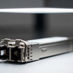
Key SDM optical specs that drive capacity and reach
SDM deployments are not just “higher capacity SFP/CFP.” Many real systems use multi-core fiber with coherent transceivers and specific optical interfaces. Even when vendors market similar reach targets, the operational envelope can differ due to receiver sensitivity, launch power limits, and crosstalk tolerance.
Representative module comparison for planning
The table below compares common coherent and short-reach optics used as planning anchors. For SDM, always verify the exact fiber type and supported interface in the vendor datasheet.
| Parameter | 10G SR (example) | 25G SR (example) | Coherent 100G/200G (planning anchor) |
|---|---|---|---|
| Typical data rate | 10 Gbps | 25 Gbps | 100G to 200G |
| Wavelength | 850 nm | 850 nm | C-band or configurable |
| Reach (typical) | 300 m (OM3), 400 m (OM4) | 100 m to 400 m (varies by class) | 10 km to 80 km+ (system dependent) |
| Connector | LC | LC | LC or MPO (platform dependent) |
| DOM / diagnostics | Commonly supported | Commonly supported | Often platform-specific |
| Operating temperature | Typically industrial ranges | Typically industrial ranges | Vendor-defined for coherent optics |
Important limitation: SDM performance depends on the full system (fiber geometry, transceiver DSP, and channel plan). Do not extrapolate reach by “wavelength class” alone. Use the vendor link calculator and confirm supported multi-core fiber types in the datasheet. For IEEE and Ethernet transport context, see [Source: IEEE 802.3]. For optics and safety, align with vendor documentation and optical interface standards from major transceiver suppliers.
anchor-text: IEEE 802.3 standard
Deployment scenario: SDM in a leaf-spine data center
Consider a 3-tier data center leaf-spine topology with 48-port 10G ToR switches at each leaf and 2x 100G uplinks to each spine. In a dense row, the cabling team is running out of conduit capacity: patch panels are constrained to a fixed number of trays, and pulling additional single-mode fiber would delay commissioning by weeks. SDM is introduced on selected spine uplink corridors to consolidate multiple spatial channels into fewer fiber bundles. The design goal is to increase effective throughput while keeping per-link insertion loss within the coherent budget and maintaining crosstalk below the receiver threshold under realistic patch panel configurations.
In field terms, the work typically includes verifying patch cord bend radius, inspecting connector endfaces, and confirming transceiver DOM alarms during warm-up. Engineers should also plan for a controlled rollout: start with one corridor, validate BER/OSNR targets, and then expand after you confirm stability across temperature swings and cleaning practices.
Pro Tip: In SDM corridors, most “mysterious” link degradations trace back to connector contamination and patch panel handling rather than the transceiver itself. Standardize endface inspection and cleaning, then treat crosstalk alarms as a physical plant clue, not only a DSP setting issue.
Selection checklist for SDM-aware network design
Use this ordered checklist during design reviews and procurement. Each item affects whether SDM will meet its OSNR/BER targets after installation.
- Distance and loss model: confirm the planned fiber length, splice loss, and worst-case patch cord count; require a vendor link budget for the exact fiber type.
- Fiber type compatibility: verify supported multi-core or spatially multiplexed fiber, including connectorization approach (LC vs MPO) and polarity rules.
- Switch and optics compatibility: confirm the exact transceiver family supported by the switch vendor; mismatches can break DOM parsing or optical power control loops.
- DSP and OSNR margin: ask for measured OSNR or sensitivity curves under crosstalk conditions; confirm thresholds for error-free operation.
- DOM and telemetry needs: ensure the platform can read vendor-specific diagnostics; define what alarms trigger maintenance.
- Operating temperature and power: match transceiver spec to the rack thermal envelope; coherent optics often have tighter limits than short-reach modules.
- Vendor lock-in risk: evaluate whether third-party optics are supported and whether firmware/DSP behavior is standardized on your platform.
Common pitfalls and troubleshooting in SDM optics
Below are frequent failure modes seen during commissioning. Each includes a root cause and a practical fix.
High error rate immediately after patching
Root cause: connector contamination or endface scratches causing elevated insertion loss and scattering.
Solution: inspect with a fiber microscope, clean with validated methods, replace suspect patch cords, and re-run link training.
BER improves, then degrades after thermal cycling
Root cause: thermal sensitivity of coherent optics plus marginal OSNR/launch power; also possible bend-induced coupling changes in routed corridors.
Solution: check bend radius compliance, verify launch power within datasheet limits, and validate with a controlled warm/cool test window.
DOM alarms but optics appear “linked”
Root cause: DOM format mismatch, unsupported transceiver diagnostics, or incorrect platform calibration causing false thresholds.
Solution: confirm transceiver part number compatibility, update switch optics profiles if the vendor supports it, and compare DOM readings against transceiver datasheet ranges.
Channel crosstalk higher than expected
Root cause: spatial alignment issues, improper fiber handling, or patch panel re-termination that increases inter-core coupling.
Solution: verify fiber handling procedures, re-terminate only with trained technicians, and recheck link crosstalk metrics using vendor tooling.
Cost and ROI note: where SDM pays off
Pricing varies widely by platform and channel count, but a realistic budget view is: third-party short-reach optics often cost less per module, while coherent SDM-capable systems and approved optics can carry a premium. OEM optics may cost 1.2x to 2.5x more than some third-party alternatives, but they frequently reduce commissioning time and compatibility risk.
TCO drivers: (1) labor hours for troubleshooting and rework, (2) downtime risk during cutovers, (3) optical spares strategy, and (4) maintenance burden from false alarms. If your constraint is conduit and patch-panel capacity, SDM can improve ROI by deferring cable plant expansion; if your constraint is already fiber abundance, SDM may not justify the higher integration complexity.
FAQ
What does SDM change in network design compared with WDM?
SDM adds spatial parallelism, so link budgets and acceptance criteria must consider crosstalk and multi-core behavior in addition to attenuation. WDM primarily changes spectral channel planning and dispersion/nonlinear management. In SDM, fiber handling and physical plant quality often dominate commissioning outcomes.
Do I need a specific transceiver for SDM?
Yes, SDM-capable coherent transceivers and DSP profiles are typically required for spatial channels to be correctly decoded. Always verify the exact fiber type and supported connectorization in the vendor datasheet and switch vendor compatibility list.
How do I validate SDM performance after installation?
Use vendor-recommended link test procedures and monitor OSNR, BER, and DOM telemetry during warm-up and after thermal changes. Compare measured values to the vendor’s tolerance ranges, not only “link up” status.
Can I mix optics vendors in the same SDM deployment?
Mixing can work in some ecosystems, but it is risky without explicit vendor support for interoperability. DOM formats, DSP behavior, and launch power control loops can differ, causing inconsistent margins across channels.
What is the fastest way to troubleshoot a failing SDM link?
Start with physical checks: connector endface inspection, cleaning, and bend radius verification. Then verify DOM readings against the transceiver datasheet and confirm platform optics profile compatibility before deeper fiber-level analysis.
Where does IEEE 802.3 fit into SDM planning?
IEEE 802.3 defines Ethernet PHY and MAC behavior for