If your access network needs more bandwidth without ripping out copper, multi-gig SFP with 2.5GBASE-T (NBASE-T) is a practical path. This article helps network engineers and field tech leads design, validate, and operate 2.5G SFP+ copper links in MDUs and campus closets. You will get a step-by-step implementation plan, selection checklist, and troubleshooting paths that match real deployment constraints.
Prerequisites: what you must verify before installing multi-gig SFP
Before you touch optics or patch cords, confirm the physical layer and operational constraints. NBASE-T over copper is sensitive to channel quality, switch port capabilities, and transceiver EEPROM settings. Plan for maintenance windows, because link negotiation failures often look like “bad optics” but are actually cabling or port-mode issues.
Hardware and documentation to gather
- Switch model and exact port type for the uplink/access tier (example: a ToR/access switch with SFP+ cages that explicitly supports 2.5GBASE-T NBASE-T).
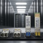
- Transceiver part numbers from vendor datasheets (example families: NBASE-T SFP+ copper modules; verify exact SKU).
- Patch panel and cable run information: cable type (Cat5e/Cat6), approximate length, and bundle conditions.
- Expected service profile: throughput targets per subscriber, oversubscription assumptions, and latency budget.
Baseline tests you should run
- Use a cable tester to measure near-end crosstalk (NEXT) and insertion loss where available; if not, at least validate continuity, pinout, and shielding.
- Confirm that your switch supports the transceiver’s negotiated rate set (for example, 2.5G forced vs auto-negotiated behavior varies by platform).
- Record ambient temperature in closets during typical load; many SFP+ copper modules have tighter thermal margins than optics.
Step-by-step deployment plan for multi-gig SFP with NBASE-T
Follow these steps in order to reduce “truck-roll” risk. Each step includes the expected outcome so you can stop early when something is misaligned.
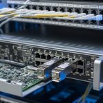
Validate switch and transceiver compatibility
Check the switch vendor’s transceiver compatibility list and confirm the port supports NBASE-T in SFP+ format. Then verify the transceiver supports the same speed modes and uses the correct management features (DOM, if you rely on monitoring). If you are mixing OEM and third-party modules, expect differences in DOM field mapping and alarms.
Expected outcome: You can insert the transceiver without “unsupported module” errors and the port stays administratively up.
Plan copper channel performance for 2.5GBASE-T
NBASE-T depends on the copper channel meeting minimum performance across frequency. In practice, Cat5e often works for many 2.5G runs, while longer or noisier links benefit from Cat6. Treat bundling and patch panel quality as first-order variables; a poorly terminated jack can reduce effective signal quality dramatically.
Expected outcome: Your planned link distances fall within the transceiver vendor’s stated reach for the specific cable class.
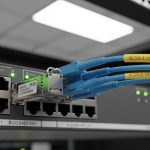
Stage and label patching for deterministic troubleshooting
Before production, stage a small test set: one switch, one transceiver pair, and representative cables (short, medium, long). Label both ends of each patch cord and patch panel port so you can correlate errors to a single channel. This matters because NBASE-T failures can be intermittent when temperature or load changes.
Expected outcome: You have a repeatable mapping between physical ports and transceiver serial numbers.
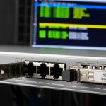
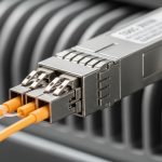
Install transceivers with correct orientation and cabling discipline
Insert the multi-gig SFP copper modules gently until the latch engages. Use locking patch cords where supported, avoid over-bending, and keep fiber rules separate from copper handling to prevent mix-ups. If your facility uses shared patch ducts, verify that copper runs are not adjacent to high-voltage cabling without proper separation.
Expected outcome: The port comes up with link established and negotiated at the intended rate.
Confirm negotiated speed, FEC behavior (if any), and monitoring
On the switch, confirm the negotiated link speed and error counters. Enable interface logging for link up/down events during the first 24 to 72 hours after install. If the transceiver supports DOM, poll temperature and optical-equivalent telemetry (some copper modules expose similar fields via vendor mapping).
Expected outcome: Interfaces show stable 2.5G operation with low error rates and no repeated renegotiations.
Roll out in MDU and campus tiers with a controlled blast radius
Start with one cabinet or one floor in an MDU, then one IDF closet in a campus. Use a staged schedule and keep spare modules on-site. If you have a monitoring system, add alerts for link flaps, CRC error spikes, and abnormal temperature readings.
Expected outcome: You reduce correlated failures and can pinpoint whether the issue is transceiver, switch port, or a subset of cables.

Technical specs you should compare before standardizing multi-gig SFP
Engineers often standardize the “copper SFP+” label, but the real differences are reach assumptions, thermal limits, connector type, and DOM support. Use the table below to compare the core properties that affect interoperability and operational reliability.
| Spec | What to check | Why it matters |
|---|---|---|
| Data rate | 2.5GBASE-T (NBASE-T) in SFP+ form factor | Prevents silent down-negotiation to 1G or link instability |
| Wavelength / optics | Not applicable (copper); no laser wavelength | Confirms you are not mixing copper and fiber module requirements |
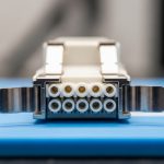
| Connector | RJ-45 copper interface on SFP+ module | Controls cabling standards and patch cord type |
| Reach | Vendor-stated reach varies by cable class (Cat5e/Cat6) and environment | Determines maximum channel length you can deploy |
| Power | Typical SFP+ copper module power is often within the SFP+ budget, but verify per datasheet | Impacts switch PSU margin in dense deployments |
| Operating temperature | Commonly industrial ranges; verify module spec and switch airflow assumptions | Reduces risk of thermal throttling and link flaps |
| DOM support | Temperature and diagnostics via vendor DOM mapping | Enables proactive replacement before failure |
Selection note: For authoritative electrical and link-layer guidance, reference IEEE Ethernet standards for 10/100/1000 and 2.5G extensions where applicable, and vendor SFP+ interface requirements. [Source: IEEE 802.3] [[EXT:https://standards.ieee.org/standard/802_3]]
Pro Tip: In the field, most “NBASE-T is flaky” incidents trace back to marginal copper channels, not the transceiver. Start by swapping only the patch cords and verifying termination quality before you replace modules; keep a known-good short cable patch as your control sample.
Real-world deployment scenario: MDU access cabinet to campus aggregation
Consider a regional provider deploying 2.5G to customer endpoints in an MDU. Each building has a small MDF with a managed access switch feeding four cabinet segments; each cabinet serves 24 apartments with uplinks using multi-gig SFP NBASE-T copper modules. In a 3-tier campus design, the access switches aggregate into an IDF that uplinks at 10G or 25G fiber, while the last-mile copper segment stays 2.5G for cost. Engineers validate each cabinet with three cable lengths (10 m, 35 m, 60 m) using representative Cat5e and Cat6 runs, then monitor CRC and link flaps for the first week.
Expected outcome: You maintain stable 2.5G links with minimal renegotiations while avoiding expensive fiber pulls inside buildings.

Selection criteria checklist for multi-gig SFP NBASE-T
Use this ordered checklist to standardize modules and reduce compatibility churn across sites.
- Distance and cable class: Confirm vendor reach for Cat5e vs Cat6, and include worst-case assumptions for bundling and patch panel quality.
- Switch compatibility: Validate the switch model and port type explicitly supports NBASE-T in SFP+ cages; avoid assumptions from “SFP+ works.”
- Negotiation behavior: Prefer designs that reliably auto-negotiate to 2.5G without forced settings; if you must force, document it.
- DOM support and telemetry: Confirm what the switch reads (temperature, alarms). If DOM mapping differs, adjust monitoring rules.
- Operating temperature: Verify both module and switch airflow conditions; closets often exceed nominal ambient during summer peaks.
- Vendor lock-in risk: If you rely on specific DOM or alarm thresholds, mixing vendors can increase operational overhead.
- Spare strategy: Keep spares sized to your rollout wave and failure rate expectations; copper modules can fail due to surge events or connector wear.
Common pitfalls and troubleshooting for multi-gig SFP link failures
When a link fails, isolate the layer quickly. The most common problems are not truly “transceiver bad,” but rather channel quality, port-mode mismatch, or thermal/connector issues.
Failure point 1: Link flaps or renegotiation loops
Root cause: Marginal copper channel (high insertion loss, poor termination, or bad patch cord) causing unstable signal quality. Temperature swings can exacerbate it after initial install.
Solution: Replace patch cords first with a known-good cable, re-terminate if possible, and compare behavior across short and long test channels. If available, use switch diagnostics for CRC and error counters to confirm improvement.
Failure point 2: Port comes up at 1G or not at all
Root cause: Switch port configuration or module negotiation mismatch, including forced speed/duplex settings that conflict with NBASE-T auto-negotiation.
Solution: Reset interface configuration to defaults for that port, remove forced speed settings, and verify the switch supports 2.5GBASE-T on that specific port type. Confirm the transceiver SKU matches the intended speed.
Failure point 3: High errors under load, then performance collapse
Root cause: Connector wear, bent cable strain relief, or electromagnetic interference from nearby power conductors. This often appears only during peak traffic when PHY margin is consumed.
Solution: Reseat modules, inspect RJ-45 terminations, improve cable routing separation, and validate with a traffic test while monitoring error counters. If errors persist, test a different cable class (Cat6) as a controlled variable.
Cost and ROI considerations for multi-gig SFP copper
In 2025 purchasing cycles, 2.5GBASE-T NBASE-T SFP+ module pricing often sits in a mid-range compared to basic 1G copper optics, but it can be cheaper than running new fiber to every small cabinet. Typical street prices vary by volume and OEM vs third-party sourcing; plan for higher TCO if third-party modules produce DOM mismatches or higher failure rates in harsh closets. ROI improves when you avoid civil work and fiber pulls, and when your monitoring can detect failing modules before they cause outages.
TCO model tip: Include labor time for swaps, downtime risk, and spare inventory carrying cost. If your rollout wave is large, negotiate spares and warranty terms that match your maintenance window constraints.

FAQ: multi-gig SFP NBASE-T questions engineers ask
What is a multi-gig SFP in this context?
Here, it means an SFP+ form-factor module that supports 2.5GBASE-T via NBASE-T over copper. It uses an RJ-45 interface and negotiates Ethernet speeds over the copper channel.
Will Cat5e always work for 2.5GBASE-T NBASE-T?
Cat5e often works for many 2.5G deployments, but reach depends on channel quality, termination, and environmental noise. Validate with vendor reach guidance and field testing for your specific building or cabinet conditions.
How do I confirm the link is truly running at 2.5G?
Use the switch interface status to check negotiated speed and monitor error counters (CRC, input errors