Upgrading a campus network to support multi-gig services often breaks on one detail: the fiber transceiver you pick for your 5GBASE-T rollout. This article helps network leads and field engineers design a reliable migration path, verify switch compatibility, and avoid avoidable downtime. You will get a step-by-step implementation guide, a concrete checklist, and troubleshooting steps for the three most common failure points.
Prerequisites: lock requirements before you touch optics
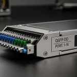
Before selecting any 5GBASE-T fiber transceiver, capture the physical layer constraints and operational targets. In practice, most failures come from mismatched optics type (SR vs LR), wrong connector geometry, or a switch that cannot negotiate the expected electrical interface. Also confirm whether you are using SFP/SFP+ style pluggables or QSFP/QSFP-DD style pluggables at the access layer, because the form factor dictates the supported speed grades.
Reference standards to ground your choices: Ethernet physical layer behavior is governed by IEEE 802.3 for the relevant PHY, and vendor optics generally document link budgets and compliance. For optics reach and interface expectations, consult vendor datasheets and the IEEE-defined link behavior for your PHY. If you are validating optics compliance, use the vendor’s Optical Link Diagnostics documentation where available.

Step-by-step implementation: deploy multi-gig fiber for 5GBASE-T upgrades
This is a build sequence that minimizes change risk during a campus migration. Each step includes an expected outcome so you can stop early if something is off.
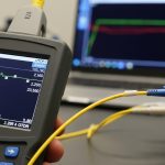
Measure distance and insertion loss for each link
Run an OTDR test on every prospective fiber path and record measured loss at the operating wavelength plus connector/patch cord losses. For short-reach campus runs, SR-class modules are common, but you must still validate that your worst-case channel loss stays within the transceiver budget. Use conservative margins for splices, patch panels, and any future re-termination.
Expected outcome: A per-link spreadsheet with measured dB loss and a clear “SR/LR class feasible” decision.
Confirm the switch and transceiver interface type
Check your switch line card documentation for supported transceiver families and DOM requirements. Many enterprise switches will accept third-party optics but may impose restrictions on DOM polling, digital signatures, or optical power reporting. If your 5GBASE-T media conversion design expects a specific fiber interface (for example, LC duplex), verify that the switch port is configured for the right speed mode and that the transceiver is in a supported DOM profile.
Expected outcome: A compatibility matrix: switch model, port type, supported optics part families, and whether third-party is allowed.
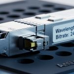
Select the correct wavelength and reach class for multi-gig fiber
For campus upgrades, you will most often see 850 nm (SR) for short reach and 1310 nm (LR) for longer spans. Your choice must match the fiber type (OM3/OM4/OM5 for multimode, or OS2 for single-mode). Vendors publish typical link budgets; treat those as starting points, not guarantees.
| Spec | SR (850 nm multimode) | LR (1310 nm single-mode) |
|---|---|---|
| Typical target reach | ~70 m (OM4 class, varies by vendor) | ~10 km (varies by vendor) |
| Fiber type | OM3/OM4/OM5 multimode | OS2 single-mode |
| Connector | LC duplex (common) | LC duplex (common) |
| Data rate support | Typically matches 5GBASE-T fiber side requirements via the platform | Typically matches 5GBASE-T fiber side requirements via the platform |
| DOM support | Often available; confirm switch polling behavior | Often available; confirm switch polling behavior |
| Temperature range | Check vendor: usually commercial or industrial variants | Check vendor: usually commercial or industrial variants |
Expected outcome: A short-list of transceiver SKUs that match fiber type, connector, and distance with margin.
Validate optics power and link stability before cutover
In the lab or on a non-critical port, insert the transceiver and verify DOM readings if available. Confirm link is up at the expected speed and that Rx power sits within the vendor’s recommended range. Then run a short traffic burn-in (for example, sustained iperf3 throughput for 30 to 60 minutes) while monitoring interface counters for CRC errors and link flaps.
Expected outcome: A stable link with clean optics diagnostics and no error counter growth.
Pro Tip: In campus deployments, the biggest “it looked fine on day one” issue is not the transceiver itself; it is patch panel re-termination tolerance. Even a small dust or angled connector can push Rx power just far enough to pass at idle but fail under bursty multi-gig traffic. Always inspect and clean LC ends immediately before insertion, and re-check DOM Rx power after any maintenance event.

Roll out in controlled batches with monitoring and rollback
Use a batch plan aligned to your maintenance windows. For each batch, track: number of affected ports, expected link class, and a rollback transceiver set that is known-good for the same interface type. Enable interface and optics monitoring (alerts on CRC errors, link down/up counts, and DOM threshold breaches) before the change.
Expected outcome: Measurable reduction in outages and fast recovery if a specific link shows abnormal loss or connector problems.
Selection criteria checklist for multi-gig fiber transceivers
- Distance and link budget: OTDR-measured worst-case loss plus margin; map to SR or LR class.
- Fiber type: OM4/OM5 for SR; OS2 for LR; confirm patch cords match.
- Switch compatibility: supported optics family list, speed mode, and DOM behavior.
- Connector and polarity: LC duplex confirmation and correct A/B orientation on duplex fibers.
- DOM support and thresholds: whether your monitoring stack expects vendor-specific DOM fields.
- Operating temperature: industrial vs commercial transceivers for outdoor or unconditioned closets.
- Vendor lock-in risk: decide between OEM optics and third-party; test third-party on a pilot batch.
When evaluating specific models, use vendor datasheets and compatibility notes. Examples of commonly referenced optics families in the market include Cisco SFP-10G-SR and Finisar FTLX8571D3BCL style SR optics, as well as FS.com SFP-10GSR-85 variants; always confirm that the exact SKU matches your platform’s supported interface and reach class. For baseline Ethernet behavior, consult IEEE 802.3 and the optics vendor’s link budget documentation. IEEE Standards ITU-T optics background references
Common mistakes and troubleshooting: the top failure modes
These are the issues you will most likely see during a 5GBASE-T fiber migration for multi-gig service delivery.
Failure point 1: Link comes up but CRC errors spike under load
Root cause: Rx power near the threshold due to dirty connectors, high insertion loss, or marginal patch cord quality. Burst traffic from multi-gig workloads exposes marginal optical budgets.
Solution: clean LC ends with lint-free swabs and proper cleaning film; re-seat connectors; verify DOM Rx power; replace suspect patch cords; re-check with OTDR if errors persist.
Failure point 2: Port flaps or stays down after transceiver insertion
Root cause: wrong transceiver type for the fiber (multimode vs single-mode), incorrect connector polarity, or switch port speed mode mismatch.
Solution: confirm fiber type and wavelength class; verify A/B polarity swap on duplex; set the port to the expected speed per switch CLI; try a known-good transceiver from the rollback pool.
Failure point 3: Third-party optics rejected or DOM monitoring breaks alarms
Root cause: switch enforces optics compatibility checks or expects specific DOM behavior; monitoring scripts rely on vendor-specific DOM field names.
Solution: run a pilot with representative third-party optics; validate DOM presence and values; update monitoring rules to accept the expected DOM schema; if required, switch to OEM optics for ports with strict policy.

Cost and ROI note for multi-gig fiber optics
Typical transceiver pricing varies widely by OEM vs third-party and by temperature grade and reach class. In many enterprise markets, OEM optics often cost about 1.5x to 3x third-party pricing, while third-party units can reduce upfront spend but increase the need for pilot testing. TCO should include: installation labor, cleaning/inspection consumables, failure replacement logistics, and downtime risk. If you experience even a small number of repeat failures due to marginal compatibility, the labor and outage cost can wipe out the initial optics savings.
Expected outcome: A procurement plan with tested optics and a cost model tied to maintenance windows and failure rates.
FAQ
What does “multi-gig fiber” mean in a 5GBASE-T campus upgrade?
It generally refers to using fiber-backed links to carry higher throughput between access switches and aggregation layers so that downstream 5GBASE-T endpoints can sustain multi-gig speeds. The transceiver selection affects link budget, stability, and error rates under bursty traffic.
Which is better for campuses: 850 nm SR or 1310 nm LR?
SR is usually best for short runs within buildings using OM4/OM5 multimode. LR is better when you need longer spans or when you are standardizing on OS2 single-mode across the campus. The decision should be driven by OTDR-measured loss and available fiber type.
Can I use third-party optics with enterprise switches?
Often yes, but you must validate compatibility with your exact switch model and software version. Confirm DOM behavior, alarm thresholds, and whether the switch enforces optics checks. Pilot at least a small batch before scaling.
How do I verify the transceiver is healthy after installation?
Check link status, speed negotiation, and DOM readings for Rx power and temperature if supported. Then monitor CRC errors, interface flaps, and any optical warnings for at least 24 hours under typical traffic patterns.
What is the fastest way to fix “link up but performance is bad”?
Start with cleaning and connector inspection, then verify DOM Rx power and compare it to the vendor’s recommended range. If the values are marginal, replace patch cords and re-check the fiber path loss with OTDR.
Should I standardize on one transceiver reach class?
Standardization reduces operational complexity, but it can increase