If you have ever swapped a transceiver and then hit “link up, but no throughput” or repeated LOS events, you already know connector choice matters. This article helps network builders and field techs decide between an MTP LC SC connector transceiver setup based on port density, polarity, and cleaning realities. You will also get troubleshooting steps that match what you see in racks and splice closures.
Connector reality check: MTP, LC, and SC on transceivers
Fiber connectors are not just “mechanical ends.” They determine how you route fiber, how you manage polarity, and how quickly you can clean and verify end faces. In practice, transceivers typically come with a specific connector interface—so choosing the connector type is choosing the transceiver form factor and cabling ecosystem. The key difference is that MTP is typically used in higher-density multi-fiber trunks, while LC and SC are common on single-fiber or per-channel interfaces.
MTP: high-density multi-fiber trunks
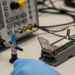
MTP connectors are usually fielded as multi-fiber arrays (commonly 12-fiber, 24-fiber). For optics, this tends to show up in data center backbone paths where you want fewer cable jackets and faster administration. Many transceiver “pigtails” with MTP are paired with structured cabling systems and pre-terminated trunks.
LC: the rack-friendly single-fiber standard
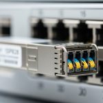
LC uses a small duplex form factor (two fibers per connector pair). It is widely used with SFP, SFP+, SFP28, and SFP56 style optics and many 10G/25G/40G/100G breakout designs. When you need dense patching close to switches, LC usually wins for ergonomics and port utilization.
SC: common in enterprise and legacy gear
SC connectors are larger than LC and typically appear in enterprise switches, media converters, and older optics deployments. If you are migrating legacy links, SC can reduce re-cabling effort, but you may lose some density compared with LC.

How to map connector choice to transceiver types and wavelengths
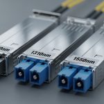
Connector type alone does not define reach; wavelength and fiber type do. In most modern deployments, the dominant decision is whether you are building multimode (OM3/OM4) short-reach links or single-mode (OS2) long-reach links. For example, 10G SR optics are typically 850 nm over OM3/OM4, while 10G/40G/100G LR optics use 1310 nm or 1550 nm over OS2.
Practical compatibility table (what field techs check)
Before ordering, confirm switch port optics requirements (SFP/SFP+/QSFP variants), fiber type, and connector mapping from your patch panel to the transceiver. Below is a quick spec-style comparison that teams often use during cutover planning.
| Connector interface | Typical transceiver family | Common wavelength | Typical reach target | Fiber type | Operating temperature |
|---|---|---|---|---|---|
| MTP (multi-fiber) | QSFP/QSFP-DD breakout with MTP trunks or MTP-to-duplex adapters | 850 nm (SR) or 1310 nm/1550 nm (varies) | 10G to 100G short-reach depending on optics | OM3/OM4 (often), OS2 (in some designs) | 0 to 70 C (typical industrial/standard) |
| LC (duplex) | SFP, SFP+, SFP28, SFP56; many QSFP breakout designs | 850 nm, 1310 nm | Up to a few hundred meters on OM4 for SR; longer on OS2 | OM3/OM4 or OS2 | -5 to 70 C to 0 to 70 C (depends on module) |
| SC | Enterprise SFP variants, media converters, legacy transceivers | 1310 nm or 1550 nm (varies) | From hundreds of meters to tens of km on OS2 | OS2 (common for longer reach) | 0 to 70 C (typical) |
Polarity and duplex rules (where outages start)
Duplex connectors carry two fibers, but polarity depends on whether the system is “straight-through” or uses a polarity scheme such as MTP cassettes with polarity adapters. If you mix polarity wrong, link light may appear while throughput collapses due to excessive bit errors. Always confirm whether your transceiver is configured for MMF SR and whether your patching uses the correct transmit/receive orientation.
Pro Tip: In the field, the fastest way to prevent polarity mistakes is to label patch cords at both ends and verify with a continuity tester before you insert optics. Even if a link “comes up,” run a quick BER check or interface counters validation—polarity errors can masquerade as partial signal issues.

Selection checklist: choosing the right MTP LC SC connector transceiver
Use this ordered checklist during planning and procurement. It reduces rework and avoids last-minute cabling swaps.
- Distance and fiber type: Match wavelength and reach to OM3/OM4 or OS2. Do not assume “SR” works on OS2.
- Port density and patching workflow: Prefer LC for dense switch panels; prefer MTP for backbone trunking and bulk administration.
- Switch compatibility: Confirm exact transceiver slot type (SFP vs SFP+ vs QSFP) and supported optical standards listed by the vendor. Check for vendor-specific quirks.
- DOM and diagnostics: If you need monitoring, ensure the module supports Digital Optical Monitoring (DOM) and that your switch reads it correctly.
- Operating temperature and airflow: In hot aisles, confirm the module’s temperature range and that airflow matches the optics vendor guidance.
- Budget and vendor lock-in risk: Compare OEM vs third-party pricing and verify compatibility lists. Plan spares because optics are not interchangeable across every platform.
Common mistakes and troubleshooting you can do today
Connector and transceiver mismatches are among the most frequent reasons for “no light” or unstable links. Here are concrete failure modes you can reproduce and fix.
Wrong polarity with MTP trunks
Root cause: MTP cassettes and polarity adapters can reverse transmit/receive if you patch the wrong way. Some links show “link up” but errors spike.
Solution: Re-check polarity labeling, then repatch using a known-good polarity diagram. Validate with counters (CRC errors) and, if available, optical power readings from DOM.
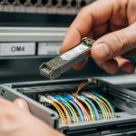
Dirty ferrules causing intermittent LOS
Root cause: Even a light film or micro-scratch on the ferrule face attenuates the signal, especially at 850 nm where cleaning sensitivity is high.
Solution: Use lint-free wipes and approved fiber cleaning tools, then inspect with a microscope/inspection scope before reinserting. Replace any connector that shows physical damage.
Connector type adapter assumptions
Root cause: People assume an MTP-to-LC adapter is equivalent to the original interface. Mechanical tolerances and polarity mapping can differ, and insertion loss increases.
Solution: Use adapters designed for the exact connector family and polarity scheme. Measure link budget expectations and confirm with vendor specs for maximum allowable insertion loss.
OS2 vs OM4 confusion
Root cause: SR optics are not interchangeable with LR optics in terms of fiber type requirements. Using the wrong fiber can cause severe attenuation.
Solution: Verify labeling on patch panels and fiber records. Confirm wavelength and transceiver type before you cut over.

Real deployment scenario: leaf-spine migration with mixed optics
In a 3-tier data center leaf-spine topology with 48-port 10G ToR switches, we migrated 24 downlinks from legacy SC patching to higher-density LC patch panels. The backbone used 12-fiber MTP trunks to reduce cable bulk across rows, while each ToR used LC for per-server patching. During cutover, we saw a brief period of CRC errors that resolved only after polarity was corrected in the MTP cassette and ferrules were re-cleaned; the interfaces otherwise reported “up.” The lesson: connector choice is a systems decision spanning patch panels, polarity adapters, and optics diagnostics.
Cost and ROI note: where the money actually goes
In many markets, third-party optics for common interfaces (LC duplex SR/SR-like) often cost roughly 30% to 60% less than OEM, but compatibility testing and higher failure rates can offset savings. OEM modules typically carry better platform validation and sometimes tighter supply-chain control. TCO depends on uptime requirements, labor time for troubleshooting, and how often you need to replace optics due to cleaning/handling damage rather than electronics failure.
If you are running high-density trunks, investing in proper MTP cassettes, labeled patching, and inspection tools can reduce outage minutes far more than chasing the lowest per-module price. Consider total cost of ownership including spare inventory and the cost of downtime during maintenance windows.
FAQ
Q: Can I use an MTP LC SC connector trans