When you are wiring a leaf-spine data center for 100G uplinks, the cabling choice between 100GBase-SR4 and 100GBase-LR4 affects port density, rack footprint, and outage risk. This guide helps network and cabling engineers plan the right MPO fiber cable type, length strategy, and optics selection for QSFP28 links. You will get a step-by-step implementation workflow, an apples-to-apples spec table, and troubleshooting patterns seen in field turn-ups.
Prerequisites: what you must know before pulling MPO fiber cable
Before ordering optics or reels, confirm your switch optics support and your fiber plant constraints. For both 100GBase-SR4 and 100GBase-LR4 QSFP28, the relevant standards are defined within IEEE 802.3 for 100G Ethernet over optical interfaces, and the QSFP28 electrical/optical behavior is governed by vendor implementation details. In practice, engineers also validate with the switch vendor’s optics compatibility list and optical budget tools. IEEE 802.3
Gather these inputs (field-usable checklist)
- Switch model and optics part numbers (for example, Cisco/Nexus, Arista, Juniper, Huawei) and the exact QSFP28 modules you plan to use.
- Link distance between each pair of endpoints, including patch panel jumper routing and slack.
- Fiber type and plant status: OM3 vs OM4 vs OS2, plus whether you already have existing MPO trunks.
- Connector policy: MPO/MTP polarity method (A/B) used in your facility, and how your patch cords map to chassis ports.
- Environmental limits: operating temperature at the top-of-rack and in underfloor or overhead cable trays.
- Optical diagnostics requirements such as DOM (Digital Optical Monitoring) support for monitoring and alerting.
Expected outcome: a short list of compatible QSFP28 optics and a confirmed fiber plant type (multimode vs single-mode) so you can size MPO fiber cable lengths correctly.
Step-by-step implementation: MPO fiber cable for 100G SR4 vs LR4
This section is written as a build plan you can hand to a cabling tech or data center contractor. The main difference is that 100GBase-SR4 is multimode and 100GBase-LR4 is single-mode; both use QSFP28 optics but typically different fiber cores, jumpers, and link loss budgets. If you mix these improperly, you will see intermittent link drops or total link failure after patching. IEEE 802.3 working group
Map the topology and measure actual end-to-end distances
In a leaf-spine deployment, do not rely only on “rack-to-rack” tape measures. Include patch panel offsets, tray routing, and slack loops to avoid exceeding the optics’ supported reach under worst-case conditions. For example, if your intended span is 85 m but the actual trunk plus patching totals 92 m, LR4 may still work while SR4 may fail depending on OM4 launch conditions and connectors. Expected outcome: a distance matrix by link pair that you can use to select SR4 or LR4 per path.
Choose fiber type and MPO fiber cable format intentionally
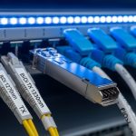
For 100GBase-SR4, you generally plan for OM3 or OM4 multimode fiber with MPO connectivity (often 12-fiber MPO trunks and 8-fiber MPO patch cords depending on polarity and MPO pinout conventions). For 100GBase-LR4, you plan for OS2 single-mode fiber with MPO connectivity. Confirm whether your facility uses MPO polarity method A or B, because wrong polarity can prevent light from reaching the receiver even if the optics and fiber are correct. Vendors document polarity behavior in their QSFP28 datasheets (and many provide polarity diagrams).
[[IMAGE:A close-up professional product photography of a 12-fiber MPO trunk cable with molded end caps, showing connector pin orientation marks, laid on a clean data center floor tile near a cable tray; neutral gray background, sharp macro lighting, shallow depth of field, high resolution, realistic textures, no logos.]
Select the QSFP28 optics type and verify vendor compatibility
Pick optics that match your fiber type and reach. A common field pattern is using SR4 modules for short intra-row links (economics and lower power) and LR4 for longer inter-row or between-rows links where pulling new multimode would be disruptive. Confirm that the switch accepts the exact module SKU and that the optics support DOM if you rely on monitoring. For example, you may encounter SR4 modules like Finisar/FS-compatible 100GBase-SR4 QSFP28 (multimode) and LR4 modules like 100GBase-LR4 QSFP28 (single-mode), but you must map to your switch’s supported list.
Build an MPO length strategy that accounts for worst-case loss
Design for worst-case link loss: include connector insertion loss, patch panel mated pairs, and aging margin. Engineers often standardize on trunk lengths (for example, 30 m or 50 m) and then use shorter patch cords to fine-tune. This reduces the chance that a “rare” long jumper consumes the remaining budget. If you are using LR4, your single-mode plant likely has lower attenuation but still requires connector cleanliness discipline.
Expected outcome: a bill of materials (BOM) that specifies MPO trunk lengths, patch cord lengths, and polarity-matched MPO patch cords so links stay within budget after installation.
Execute polarity and labeling before you energize
Before connecting to live switches, validate polarity end-to-end with a continuity/optical test procedure. Label each MPO trunk and each patch cord with link ID, polarity method, and endpoint mapping (leaf switch port to spine switch port). This prevents the classic “all links down” scenario where optics are fine but MPO polarity is reversed across patch panels. Expected outcome: consistent polarity across all patch points and a clear restoration path if a link fails.
Turn up links with diagnostics and verify optical power/DOM
After patching, bring up interfaces and check link state, then read DOM values if supported. Many operators log receive power, transmit power, and error counters (for example, CRC and symbol errors) to confirm stable operation. If you see marginal receive power, clean connectors first and then inspect for bent fiber or damaged jacket at cable tray transitions. Expected outcome: stable 100G links with acceptable error rates and optical levels within vendor recommended ranges.

100GBase-SR4 vs 100GBase-LR4 QSFP28: key differences that drive MPO cabling
The decision is not just “reach.” It is also fiber type (OM vs OS), connector behavior, installation cost, and how often you expect to reconfigure ports. SR4 typically fits dense, shorter runs using multimode plants; LR4 enables longer spans and more flexibility when you expect growth or frequent moves. Both use QSFP28 and typically four lanes in parallel, but the wavelength plan differs, which affects how you test and troubleshoot. [Source: IEEE 802.3, vendor QSFP28 datasheets]
Specifications comparison (practical planning view)
| Spec item | 100GBase-SR4 (QSFP28) | 100GBase-LR4 (QSFP28) |
|---|---|---|
| Primary fiber type | OM3 or OM4 multimode | OS2 single-mode |
| Typical wavelength band | 850 nm nominal (multimode) | ~1310 nm nominal (single-mode) |
| Typical connectorization | MPO/MTP (often 12-fiber trunks) | MPO/MTP (often 12-fiber trunks) |
| Reach (typical) | Up to ~100 m on OM4 (vendor-dependent) | Up to ~10 km (vendor-dependent) |
| Power use (typical) | Often lower than LR4 (varies by vendor) | Often higher than SR4 (varies by vendor) |
| DOM support | Common; verify per SKU | Common; verify per SKU |
| Operating temperature | Typically commercial or industrial grades; verify per module | Typically commercial or industrial grades; verify per module |
Expected outcome: a clear mapping of which links use SR4 with OM4 MPO trunks versus LR4 with OS2 MPO trunks, based on distance and existing fiber.
Pro Tip: In MPO-based plants, most “mystery” 100G failures after a patch are polarity or connector cleanliness issues, not optics incompatibility. Before swapping expensive QSFP28 modules, inspect MPO end faces under magnification and confirm polarity mapping across every patch panel transition. This single workflow routinely cuts downtime in live data center cutovers.
Deployment scenario: leaf-spine build with mixed SR4 and LR4
Consider a 3-tier data center leaf-spine topology with 48-port 100G ToR switches and 32-port spine switches. Each ToR has 8 uplinks to the spine over 100G, and the cabling team installs 40 m trunks for intra-row links using OM4 multimode MPO fiber cable for SR4, while inter-row links that route around fire breaks total 3.5 km of routed fiber and use OS2 MPO fiber cable for LR4. In the first phase, the contractor uses standardized MPO trunks (for example, 50 m) plus patch cords to hit exact port pairs; in the second phase, relocation of ToR ports is handled by swapping only patch cords while leaving trunks in place. In this scenario, SR4 reduces optics cost and power for the short paths, while LR4 avoids disruptive reruns for the long paths.
[[IMAGE:Conceptual illustration in isometric view of a data center row with leaf switches and a spine switch, showing two color-coded MPO fiber cable routes: orange for OM4 SR4 short links and blue for OS2 LR4 long links; include labeled distances (40 m and 3.5 km), clean vector style, crisp lines, flat shading, light grid background, no real brand logos.]
Selection criteria: how engineers decide SR4 or LR4 for MPO fiber cable
Procurement decisions should be grounded in measurable constraints rather than assumptions. Use this ordered checklist during design review and before issuing purchase orders. If you do not have complete plant loss data, treat the budget as “worst-case” and add margin for connector variability and future patching.
- Distance and routing reality: choose SR4 for paths comfortably under the vendor reach with margin; choose LR4 when routed distance or growth plans exceed SR4’s practical budget.
- Fiber plant type: do not plan SR4 on OS2 or LR4 on OM3/OM4; multimode vs single-mode mismatch is a common procurement error.
- Switch compatibility and optics SKU lock-in: verify with the switch vendor compatibility matrix; maintain a controlled alternates list to reduce future RMA variability.
- DOM support and monitoring workflow: if you depend on telemetry, confirm DOM is supported and that your NMS reads it reliably.
- Operating temperature and thermal path: validate module grade for the environment (top-of-rack can be hotter than room average).
- MPO polarity and patch panel standardization: align your polarity method across trunks and patch cords; standardize labels and port maps.
- Power and cooling impact: LR4 optics can increase power per port; aggregate power across hundreds of 100G ports when computing TCO.
- Supply chain risk: qualify at least two approved module sources and keep a buffer stock for cutover windows.

Common mistakes and troubleshooting: SR4 vs LR4 link failures
Field issues usually cluster into a few repeatable failure modes. Below are the top pitfalls engineers encounter when deploying MPO fiber cable with QSFP28 SR4 and LR4.
Troubleshooting failure point 1: Wrong polarity across patch panels
Root cause: MPO polarity A/B mismatch or incorrect orientation during patch cord installation results in light not reaching the intended lane mapping. Symptoms: QSFP28 shows link down or flaps after initial up; DOM may show low/zero receive power. Solution: confirm polarity diagrams from the optics and patch cord standard, then swap patch cords end-for-end or replace with polarity-correct MPO cords; re-test with a known-good link pair.
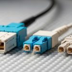
Troubleshooting failure point 2: Connector contamination on MPO end faces
Root cause: MPO end faces get micro-dust or oils during handling, especially when patch cords are repeatedly connected during cutovers. Symptoms: link intermittently drops, higher error counters, or receive power near threshold. Solution: clean using approved MPO cleaning tools, inspect under magnification, and re-seat connectors; only after cleaning should you consider optics replacement.
Troubleshooting failure point 3: Fiber type mismatch or wrong attenuation budget assumptions
Root cause: SR4 optics installed on single-mode OS2 or LR4 optics installed on OM3/OM4; or the link is built longer than the vendor reach once patch cords and extra connectors are included. Symptoms: consistent link failure (never comes up) or excessive receive power margin loss. Solution: verify fiber type at the patch panel (label and test), measure actual jumper lengths, and use vendor loss calculators with connector counts; rebuild with correct fiber or switch to LR4/SR4 per path.
Cost and ROI note: budgeting MPO cabling plus optics over the life of the site
Pricing varies by region and vendor qualification status, but a realistic planning approach is to compare optics cost and expected downtime costs, not just sticker price. In many deployments, SR4 optics are less expensive than LR4 optics, and SR4 typically uses lower-power multimode electronics, which can reduce operating expense at scale. However, if you choose SR4 where LR4 is required, the ROI collapses due to rework, extended cutovers, and increased failure rates from repeated reconnections. TCO should include: optics purchase, MPO trunks and patch cords, cleaning consumables, planned spare optics, and labor for testing.
Procurement guidance: source approved optics SKUs and keep at least a small pool of spare modules and key patch cord lengths for turn-up windows. Also, consider supply chain lead times for qualified optics; for large rollouts, buffer stock can prevent schedule slips during peak demand.
[[IMAGE:Photographic lifestyle-style scene inside a server room during a maintenance window, showing a field engineer wearing ESD-safe gloves inspecting an MPO connector end face with a fiber inspection microscope; include a laptop with a generic network monitoring dashboard glow, soft overhead lighting, candid documentary style, shallow depth of field, no brand logos.]
FAQ: SR4 vs LR4 QSFP28 and MPO fiber cable purchasing questions
Q1: Can I use the same MPO fiber cable for both 100GBase-SR4 and 100GBase-LR4?
No. SR4 requires multimode OM3/OM4 fiber, while LR4 requires single-mode OS2. MPO is the connector format; it does not change the underlying fiber type and optical physics.
Q2: What is the most common reason a 100G MPO link stays down after patching?
The most common causes are MPO polarity reversal and contamination on the MPO end face. Validate polarity mapping across patch panels and clean/inspect connectors before swapping optics.
Q3: How do I decide SR4 vs LR4 when distances are borderline?
Use the vendor reach with a conservative loss budget that includes patch cords and connector pairs, and then add margin for future re-patching. If you cannot confidently stay within margin, choose LR4 for that path to reduce operational risk.
Q4: Do I need DOM for troubleshooting SR4/LR4 MPO links?
DOM is strongly recommended because it provides transmit/receive diagnostics that help distinguish optics issues from cabling issues. If DOM is unavailable, you will rely more heavily on BER counters, link flaps, and physical inspection.
Q5: Are third-party QSFP28 optics safe for production?
They can be safe if they are from approved vendors and match your switch compatibility list, but compatibility and DOM behavior vary by SKU. Always qualify with a pilot and validate monitoring, temperature grade, and optics diagnostics in your environment.
Q6: What spare items should procurement include for MPO fiber cable turn-ups?
Include spare QSFP28 modules (at least for the most critical paths), a small kit of polarity-correct MPO patch cords in the most common lengths, and approved cleaning tools. This reduces downtime when connectors are contaminated or when a cutover requires fast rollback.
With a disciplined MPO fiber cable plan—distance mapping, fiber type alignment, polarity consistency, and DOM-enabled verification—you can deploy 100GBase-SR4 and 100GBase-LR4 with predictable outcomes. Next, review How to size patch cords and MPO polarity for QSFP28|How to size patch cords and MPO polarity for QSFP28 to standardize your patch panel workflow.
Author bio: I have led fiber and optics rollouts in multi-row data centers, validating QSFP28 link budgets with DOM telemetry and connector inspection workflows. My procurement reviews focus on compatibility matrices, lead time risk, and repeatable turn-up procedures that field engineers can execute under cutover pressure.