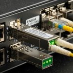
Picking a `packet transport SFP` for an MPLS-TP packet transport network is where “it should work” goes to die. This guide helps network engineers and field techs select the right optics for a real topology, avoid DOM and link-margin surprises, and troubleshoot the classic failure modes before your NOC starts sweating. You will get practical selection criteria, compatibility caveats, and a checklist you can actually use during installs.
Why MPLS-TP cares about the exact packet transport SFP
MPLS-TP (MPLS Transport Profile) runs over packet networks, so your transceiver choice directly affects link availability, error rate, and timing stability for pseudowires and OAM. In practice, “wrong optics” usually shows up as flapping links, high BER, or a vendor refusing to initialize optics due to DOM or EEPROM data mismatches. Your SFP must match the switch’s expected electrical interface (SFP/SFP+ management), the fiber type, and the optics budget.
For most enterprise and metro MPLS-TP deployments, engineers standardize on known optics families: 10G SR over OM3/OM4, 10G LR over single-mode, and sometimes 25G variants when the platform supports it. But the selection trap is that reach ratings are not guarantees; they assume a specific fiber attenuation, connector loss, and a typical transmitter/receiver power window defined by the vendor’s datasheet.
Field reality: optics budget beats marketing reach
When you plan a circuit, treat the SFP as an optical power budget problem, not a “distance label” problem. Assume worst-case attenuation for the fiber span and add connector/mated-patch losses. If the link budget is tight, you can pass initial link bring-up and still fail later under temperature swings, dirty connectors, or fiber aging.
Pro Tip: In many switch platforms, DOM values are used for optics qualification and alarm thresholds. If you use third-party optics, a DOM implementation that reports slightly different calibration data can trigger receiver power alarms even when the link is physically up. Always validate DOM behavior during commissioning, not just on day one.
Packet transport SFP specs that actually change your link
Below is a practical comparison of common packet transport SFP optics used in MPLS-TP style transport. Use it as a starting point, then confirm exact parameters in your switch vendor’s optics compatibility list and the SFP vendor datasheet.
| Optics type | Typical wavelength | Target reach | Fiber + connector | Data rate | Avg Tx power / Rx sensitivity (typ.) | DOM | Operating temperature | Example part numbers |
|---|---|---|---|---|---|---|---|---|
| 10G SR | 850 nm | Up to 300 m (OM3) / 400 m (OM4) | Multimode, duplex LC | 10.3125 Gb/s (10G) | Tx about -4.5 to 0 dBm class; Rx sensitivity about -11 to -14 dBm class | Yes (SFF-8472) | 0 to 70 C (typical) | Cisco SFP-10G-SR, Finisar FTLX8571D3BCL, FS.com SFP-10GSR-85 |
| 10G LR | 1310 nm | Up to 10 km | Single-mode, duplex LC | 10.3125 Gb/s | Tx about 0 to +3 dBm class; Rx sensitivity about -14 to -16 dBm class | Yes (SFF-8472) | -5 to 70 C or 0 to 70 C class | Finisar/FS.com 10G LR families; check switch list |
| 25G SR (if platform supports) | 850 nm | Up to ~100 m (OM3) / ~150 m (OM4) class | Multimode, duplex LC | 25.781 Gb/s (25G) | Tx about -2 to +2 dBm class; Rx sensitivity about -10 to -14 dBm class | Often yes (platform dependent) | 0 to 70 C typical | 25G SFP28 SR optics (verify your exact SKU) |
Notes: the table shows typical ranges; exact values vary by vendor SKU. For standards alignment, most SFP optical modules use SFF-8472 for digital diagnostics. Switch side behavior is governed by the platform’s firmware and its supported optics list. For Ethernet physical layer references, see IEEE 802.3 for 10G/25G link definitions and module electrical/optical expectations. [Source: IEEE 802.3] [Source: SFF-8472 Digital Diagnostic Interface]
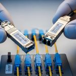
Connectors and fiber types: the silent killers
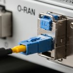
Most packet transport SFP deployments use duplex LC connectors. Multimode SR optics require OM3/OM4 fiber; using OM2 can be a “works for a week, fails during winter” situation. If you are on single-mode LR, confirm you have UPC/APC polarity handling and correct transmit/receive mapping—yes, polarity still matters even when everyone swears they labeled the patch panels.

Selection checklist: from MPLS-TP requirements to a shippable optic
Use this ordered checklist like a mini acceptance test. It is designed for rapid validation during installs, not theoretical debates.
- Distance and fiber attenuation: compute worst-case attenuation (fiber spec + connectors + patch cords). Use vendor power budget guidance for the exact optics SKU.
- Wavelength and fiber type: SR typically 850 nm on OM3/OM4 multimode; LR typically 1310 nm on single-mode. Do not mix.
- Data rate and platform support: confirm the switch port supports the optics form factor and speed. Some platforms accept only specific SFP/SFP+ generations.
- DOM and alarms: verify SFF-8472 compatibility and that DOM thresholds align with your monitoring. Validate receiver power readings under normal temperature.
- Operating temperature and airflow: check module temp range and ensure your rack airflow matches the switch’s thermal design. Tight margins show up as late-life failures.
- Vendor lock-in risk: test third-party optics in a pilot. Some vendors enforce optics qualification or apply conservative alarm thresholds.
- Optical polarity and patch panel mapping: confirm Tx/Rx direction and labeling. Use a light source and power meter if there is any doubt.
- OAM and maintenance windows: schedule validations for MPLS-TP services. A “link up” does not mean “service stable” if error counters spike.
Quick decision shortcuts that engineers actually use
If you are within a data center and have OM4, SR is often the lowest-cost reliable choice for packet transport SFP. If you are spanning metro distances over single-mode, LR (or ER/ZR if required) is usually the safer bet, but confirm dispersion and connector cleanliness. For any tight budget, prefer optics with stronger receiver sensitivity and validate DOM receiver power against vendor recommended operating ranges.
Compatibility and standards: what to verify before you rack it
In MPLS-TP packet transport networks, the transceiver is part of a system: switch ASIC + firmware + optics module + fiber plant. Start with the switch’s optics compatibility list, then verify module diagnostics interface behavior. SFP modules commonly implement SFF-8472 digital diagnostics, and Ethernet physical layer requirements are described in IEEE 802.3. [Source: IEEE 802.3] [Source: SFF-8472 Digital Diagnostic Interface]
Switch-side checks during commissioning
- Confirm link negotiation and lane/encoding status via platform CLI.
- Check DOM: vendor/model fields, temperature, Tx power, Rx power, and “alarm/warning” flags.
- Monitor error counters (CRC, FCS, alignment or PCS errors depending on platform).
- Run a sustained traffic test long enough to cover warm-up and temperature drift (for example, 30 to 120 minutes).

Common mistakes and troubleshooting tips (the stuff that wastes weekends)
Here are failure modes that show up repeatedly in packet transport SFP deployments. Each includes the root cause and a practical fix.
Link flaps after optics warm-up
Root cause: Receiver power margin is too tight, often due to higher-than-expected fiber attenuation or dirty connectors. Temperature drift can push the optical link past receiver sensitivity. Solution: Clean connectors, verify polarity, then measure Rx power with the switch DOM and compare to vendor recommended ranges. If margin is still tight, reduce patch cord loss or move to a different optics class (for example, LR vs SR).
“Unsupported transceiver” or DOM alarms with third-party optics
Root cause: Switch firmware enforces an optics vendor/model allowlist or expects specific DOM fields/calibration behavior. The module may still be electrically compatible but fails qualification. Solution: Pilot the exact optic SKU in the target switch. Confirm DOM fields populate correctly and that alarm thresholds do not trip during normal operation. If needed, use vendor-matched optics or an OEM/authorized third-party with proven compatibility.
Works on one port, fails on another port in the same switch
Root cause: Port-specific optics calibration, transceiver cage issues, or a marginal bend/strain in a fiber patch. Another port may have different electrical equalization settings. Solution: Swap optics between ports to isolate whether the issue follows the module or the port. Inspect patch cords for strain relief, re-terminate if needed, and verify that the cage contacts are clean and fully seated.
High BER even though link is “up”
Root cause: Wrong fiber type (multimode vs single-mode), incorrect wavelength class, or contaminated optics surfaces causing increased optical loss. Solution: Confirm SFP wavelength class (850 vs 1310) and fiber type on the patch panel. Clean using proper optical cleaning tools and re-test with sustained traffic while watching error counters and DOM Rx power.
Cost and ROI note: what you actually pay for packet transport SFPs
Realistic street pricing varies by speed and vendor, but for budgeting: 10G SR optics often land in the approximate range of $30 to $120 per module depending on brand and temperature grade; OEM-branded modules can cost more. 10G LR optics are commonly $60 to $200. Third-party modules may be cheaper, but the ROI depends on compatibility and failure rates.
In a typical metro aggregation site with, say, 24 to 96 active optics, TCO is dominated by spares, downtime risk, and the labor cost of troubleshooting. If third-party optics reduce module cost by 30% but increase commissioning time or cause intermittent DOM alarms, your “savings” evaporate faster than a packet in a black hole. Plan a pilot batch, measure commissioning hours, and track field failures over a defined period.

FAQ: MPLS-TP packet transport SFP buying questions
What does “DOM compatible” mean for packet transport SFP?
DOM refers to the digital diagnostics interface (commonly SFF-8472). It typically provides temperature, Tx power, Rx power, and alarm/warning indicators. You still need to confirm your switch firmware accepts and correctly interprets the DOM data from that specific optic SKU. [Source: SFF-8472 Digital Diagnostic Interface]
Can I mix SR and LR optics on the same MPLS-TP link?
No. Both ends must use compatible optics: matching wavelength class and correct fiber type (multimode SR vs single-mode LR). Even if the link “connects,” mismatched optics can cause high BER or total failure after warm-up. Always verify the patch panel labels and fiber type.
How do I estimate whether reach is enough for my span?
Use the vendor’s optical power budget for the exact module and your fiber attenuation and connector loss assumptions. Then validate with DOM Rx power during commissioning under normal temperature. If you are near the edge, prefer an optics class with better sensitivity or shorten the effective path.
Are third-party packet transport SFP modules safe to deploy?
They can be safe if the exact SKU is validated on your exact switch model and you confirm DOM behavior and alarm thresholds. Run a pilot, monitor error counters and DOM Rx power for at least a few hours, and keep OEM optics as fallback for critical links until you build confidence.
What are the fastest troubleshooting steps when a link won’t come up?
First, check that the optics are fully seated and the connector polarity matches. Next, confirm fiber type and wavelength class, then clean connectors and re-test. Finally, review switch logs and DOM fields to see whether the receiver is seeing power or if the platform is rejecting the module.
Where can I check standards and module expectations?
Start with IEEE 802.3 for Ethernet physical layer requirements and SFF-8472 for DOM expectations. Then rely on your switch vendor’s optics compatibility list and the SFP module datasheet for exact power and temperature specs. [Source: IEEE 802.3] [Source: SFF-8472 Digital Diagnostic Interface]
Choosing a packet transport SFP for MPLS-TP is mostly about matching optics to fiber plant, validating DOM behavior, and ensuring you have real link margin—not just a spec-sheet reach number. Next step: review your switch optics compatibility list and shortlist two candidate SKUs, then run a pilot validation with DOM and sustained traffic before you scale. packet transport SFP deployment checklist
Author bio: I have deployed and troubleshot metro packet transport optics in live data centers, including DOM-driven alarm tuning and optical power margin validation. I write guides that optimize for PMF: ship fast, measure hard, and stop guessing.