AI training and inference clusters fail in practical ways: link flaps from marginal optics, thermal throttling in dense racks, and silent incompatibilities between switch firmware and transceivers. This article helps network and infrastructure engineers choose ML optics (fiber transceivers) that behave predictably from bench tests to production. You will get a top list, a specs comparison table, a decision checklist, and troubleshooting patterns field teams actually see.
Top 8 ML optics picks: match distance, fiber, and switch behavior
For ML workloads, the “best” transceiver is the one that meets reach, optical budget, and operating temperature while aligning with your switch’s optics compatibility rules. In practice, most AI clusters use multi-lane interfaces (10G/25G/40G/100G depending on NIC and ToR design) over OM4/OM5 or OS2 fiber. Vendor-qualified modules often reduce risk, but third-party parts can work if they support the same electrical interface and DOM handling.
10G SR (850 nm) for short ToR aggregation
Key specs: typically 10G Ethernet over MMF 850 nm, commonly OM4, with reach around 300 m (OM4) depending on implementation. Examples include Cisco SFP-10G-SR and Finisar/FS-branded 10G-SR SFP+ modules. Best-fit: leaf-to-spine or ToR-to-server links inside a data hall where patch cords and short trunk runs dominate.
- Pros: lowest cost per port; mature ecosystem
- Cons: limited reach; higher fiber count than long-reach schemes

25G SR (850 nm) for modern 25G server NICs
Key specs: 25G over MMF at 850 nm; OM4 reach commonly about 70 m–100 m depending on link margin and module class. Many AI racks now standardize on 25G ToR because it balances cost and performance versus 40/100G. Best-fit: connecting GPU servers to ToR when your cable plant is mostly OM4 and you can keep patching short.
- Pros: strong price/performance; widely supported by ToR vendors
- Cons: can be sensitive to excessive patch loss and dirty connectors
40G SR4 (850 nm) for legacy aggregation blocks
Key specs: 40G SR4 uses four lanes over MMF at 850 nm. Typical OM3/OM4 reach varies; OM4 is usually the safe baseline for many deployments. Best-fit: when you inherit older 40G aggregation switches or uplinks and need continuity while upgrading gradually.
- Pros: efficient for existing 40G optics
- Cons: more lanes and sometimes higher power; less future-proof than 25/100G
100G SR4 (850 nm) for high-density ToR uplinks
Key specs: 100G over MMF with four lanes; reach often around 100 m (OM4) depending on optics and host channel. In dense AI halls, 100G SR4 reduces the number of uplinks while staying within typical intra-building distances. Best-fit: spine uplinks from ToR where fiber runs are short and you can manage optics quantity and spares.
- Pros: high throughput per port; common in modern switch stacks
- Cons: connector cleanliness and link margin matter more than on shorter-rate links
100G FR1 / LR1 (1310/1311 nm) for intra-campus runs
Key specs: single-mode long-wave variants at ~1310/1311 nm target longer reach on OS2. In many designs, 2 km–10 km classes exist depending on whether you choose FR1 or LR1 optics. Best-fit: connecting buildings or rows where trenching and patching create multi-kilometer paths.
- Pros: reduces fiber count using SMF; better for campus distance
- Cons: higher module cost; requires careful OS2 budgeting and splice quality

100G DWDM grid optics (where you need scale beyond “single lambda”)
Key specs: Dense Wavelength Division Multiplexing (DWDM) uses multiple wavelengths to multiply capacity over one fiber pair. Practical deployments rely on a defined ITU grid and transceiver pairing with a mux/demux. Best-fit: when you must add capacity but cannot pull more fiber due to permitting or infrastructure constraints.
- Pros: maximum capacity over limited fiber
- Cons: operational complexity; requires stable wavelength plans and careful vendor alignment
25G/100G “extended temp” optics for hot aisles
Key specs: extended operating temperature modules often support ranges that exceed standard commercial limits (commonly needed near exhaust heat paths). In AI halls, airflow patterns can be uneven, and optics can become the limiting factor even when switches throttle late. Best-fit: deployments with side-by-side GPU racks where intake temperatures spike during peak training windows.
- Pros: fewer field returns caused by thermal stress
- Cons: sometimes higher price and stricter handling requirements
Coherent optics (special case for long reach and aggregation)
Key specs: coherent transceivers can reach tens of kilometers and support advanced modulation, but they are usually used for backbone aggregation rather than ToR-to-server. Best-fit: when you are building a campus-wide AI fabric spanning data centers and need reach plus spectral efficiency. Note: coherent optics are not typical ML optics for rack-level GPU networking.
- Pros: long reach and scalable bandwidth
- Cons: higher cost; more link engineering and optics management
Specs that matter: a practical ML optics comparison table
Engineers compare optics on wavelength band, fiber type, reach, connector style, electrical interface, DOM support, optical power class, and temperature. The table below summarizes common choices for AI deployments; exact reach depends on switch channel design and fiber plant loss. Always confirm alignment with IEEE Ethernet PHY requirements and your switch’s transceiver compatibility list.
| ML optics type | Wavelength | Data rate | Fiber | Typical reach | Connector | DOM | Temperature range (typ.) |
|---|---|---|---|---|---|---|---|
| 10G SR SFP+ | 850 nm | 10G | OM4 MMF | ~300 m | LC | Yes (monitoring) | 0 to 70 C |
| 25G SR SFP28 | 850 nm | 25G | OM4 MMF | ~70–100 m | LC | Yes | 0 to 70 C |
| 40G SR4 QSFP+ | 850 nm | 40G | OM4 MMF | ~100 m class | LC | Yes | 0 to 70 C |
| 100G SR4 QSFP28 | 850 nm | 100G | OM4 MMF | ~100 m class | LC | Yes | 0 to 70 C |
| 100G LR1 QSFP28 | ~1310–1311 nm | 100G | OS2 SMF | ~10 km class | LC | Yes | -5 to 70 C (varies) |
Standards pointers: Ethernet PHY behavior is defined by IEEE 802.3 families for the relevant rates; transceiver management and vendor DOM behavior commonly follow industry monitoring conventions described in vendor datasheets. For authoritative baseline references, see IEEE 802.3 standard portal and typical module datasheets from switch and optics vendors such as Cisco and Finisar. [Source: IEEE 802.3]
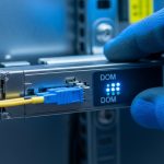
Pro Tip: In AI clusters, treat DOM alarms as operational signals, not decoration. If you see transmit power drifting toward the module’s lower limit while receive power simultaneously trends down, the root cause is often connector contamination or micro-bending in patch cords, not “bad optics.” Field teams fix this by cleaning LC faces, re-terminating only the suspect patch segment, and re-running BER counters after the change.
Selection checklist for ML optics in AI/ML infrastructure
Use this ordered checklist to avoid late-stage surprises during burn-in and change windows.
- Distance and topology: measure from transceiver to transceiver including patch cords, splitters, and splices.
- Fiber type and plant loss: confirm OM4 vs OM5 and OS2 grade; validate with OTDR or certified loss reports.
- Switch compatibility: verify the exact transceiver part number is supported by your switch model and firmware.
- Rate and lane mapping: ensure correct form factor (SFP+, SFP28, QSFP+, QSFP28) and lane count (SR4 vs SR2 vs single-lane).
- DOM support and monitoring: confirm DOM polling works in-band and that thresholds won’t trigger false alarms.
- Operating temperature: prefer extended-temp modules for hot aisles; confirm airflow direction and intake temps.
- Vendor lock-in risk: balance OEM-qualified modules against third-party options with documented compatibility.
Real-world deployment: ML optics in a 3-tier AI fabric
In a 3-tier data center leaf-spine topology with 48-port 25G ToR switches and 8 uplinks at 100G, a team deployed 25G SR to connect 2,048 GPU servers across 42 racks. All ToR-to-server links used OM4 with patch runs under 15 m, while ToR-to-spine used 100G SR4 over consolidated patch panels with a target of < 1.5 dB additional loss per trunk segment. After rollout, they observed link resets during peak heat; root cause was optics operating near the upper temperature boundary, so they swapped in extended-temp ML optics and adjusted rack airflow. Post-change BER counters stabilized and DOM telemetry stopped showing rising error indications.
[[IMAGE:Photorealistic lifestyle scene inside a data center aisle: engineers in ESD-safe attire holding a fiber cleaning kit and an SFP28 module, orange cable ties, LED strip lighting, shallow depth of field, documentary style