If your Ericsson microwave backhaul is acting up, the culprit is often boring: the wrong MINI-LINK SFP type, a reach mismatch, or a module that simply refuses to behave at the temperature your site actually experiences. This article helps network engineers, field techs, and procurement folks choose the right SFP variant, plan for compatibility, and estimate total cost of ownership (TCO) without gambling on “it should work.” You will get practical selection criteria, a deployment scenario with real numbers, and troubleshooting steps rooted in how these links fail in the wild.
How MINI-LINK SFP modules fit Ericsson microwave backhaul
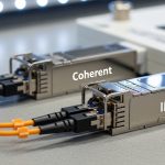
In Ericsson microwave networks, the optical interface between baseband equipment and transport gear often uses pluggable optics. A MINI-LINK SFP is typically the small form-factor transceiver that provides the optical transmit and receive functions over fiber, translating electrical serial data into light that traverses the link. In practice, you are aligning three things: the microwave system’s expected electrical interface, the fiber plant’s physical layer parameters, and the optics’ transmitter/receiver characteristics.
Most deployments use standards-based optical performance aligned with IEEE 802.3 Ethernet PHY behavior, while the exact module selection depends on the microwave platform’s port expectations and supported transceiver types. Ericsson’s internal transceiver guidance (often provided in vendor documents and platform-specific guides) emphasizes that the module must match the required wavelength (commonly 850 nm for short reach multimode or 1310 nm for longer reach single-mode in many architectures) and the supported data rate.
What “compatibility” really means in the field
Compatibility is not just “same connector.” It includes signal format, optical budget, link margin, and how the chassis reads module diagnostics. Many modern SFPs expose diagnostics via Digital Optical Monitoring (DOM), including transmit power, receive power, bias current, and temperature. Engineers often discover that a module can physically click in, but still fail link stability because the microwave equipment expects a certain initialization behavior or DOM presence.
Pro Tip: During swaps, do not trust “link up” as your only success criterion. Record DOM values (Tx power and Rx power) at commissioning and after 24 hours. A marginal module can pass initial negotiation but drift with temperature, especially on rooftop cabinets where thermal cycling is ruthless.

Key MINI-LINK SFP specs that decide whether the link survives
Choosing the right MINI-LINK SFP boils down to matching wavelength, reach, and data rate to the actual link budget. Even when your fiber looks “fine,” you can lose margin from connector contamination, patch panel losses, or aging. Below is a practical comparison of common SFP types you will see in backhaul and enterprise transport contexts.
| Parameter | 10G SR (MMF) | 10G LR (SMF) | 10G ER (SMF) |
|---|---|---|---|
| Typical Wavelength | 850 nm | 1310 nm | 1550 nm |
| Typical Reach | 300 m (OM3) / 400 m (OM4) | 10 km | 40 km |
| Data Rate | 10.3125 Gb/s (10G Ethernet) | 10.3125 Gb/s | 10.3125 Gb/s |
| Connector | LC (usually) | LC (usually) | LC (usually) |
| Optical Fiber | Multimode (OM3/OM4) | Single-mode | Single-mode |
| DOM Support | Common (Tx/Rx power, temp) | Common (Tx/Rx power, temp) | Common (Tx/Rx power, temp) |
| Operating Temperature | Often -5 to 70 C (commercial) or wider for industrial | Often -5 to 70 C or industrial variants | Often -5 to 70 C or industrial variants |
| Typical Power Budget Behavior | Limited by MMF link losses | Budget tolerant with SMF | Higher budget, long-haul capable |
Those figures are typical, not guaranteed. For example, a Finisar or FS.com module may advertise nominal reach based on a reference link with specific fiber type and attenuation assumptions. Always verify the module datasheet and the chassis’ supported optics list for the Ericsson platform you are working on.
Real module examples you might encounter
In the field, engineers often evaluate known part numbers for baseline behavior. Examples include Cisco SFP-10G-SR and Finisar FTLX8571D3BCL (10G SR variants), plus third-party equivalents like FS.com SFP-10GSR-85. The ROI angle: known-good modules reduce commissioning time and minimize “mystery failures,” but third-party options can still be viable if they match the vendor’s documented compatibility requirements and pass DOM checks.

Selection checklist: picking the right MINI-LINK SFP without buying regret
When a microwave link depends on a MINI-LINK SFP, selection is a risk management exercise. Use this ordered checklist like a pre-flight inspection before you ship modules to a tower site with no spare time and worse coffee.
- Distance and fiber type: Confirm MMF vs SMF, and the expected reach. For MMF, verify OM3 vs OM4; for SMF, confirm connector cleanliness and attenuation.
- Wavelength alignment: Ensure the module wavelength matches the link plan and the remote end. A 850 nm SR module on a path planned for 1310 nm will not magically work.
- Data rate and Ethernet mode: Confirm the microwave transport expects 10G Ethernet, 1G, or other rates. Mismatched PHY rate can lead to no link or unstable link.
- Switch or chassis compatibility: Check the Ericsson platform’s supported optics guidance. Some systems are strict about vendor ID, DOM behavior, or specific optical parameters.
- DOM support and monitoring expectations: Verify that the module provides the expected DOM fields and that the chassis reads them without faulting.
- Operating temperature and thermal cycling: Use industrial-grade modules for outdoor racks. Rooftop cabinets can swing rapidly between day and night.
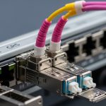
- Connector type and cleaning plan: Confirm LC vs other connector formats and ensure you have lint-free wipes and proper cleaning tools.
- Vendor lock-in risk: If you rely on OEM-only optics, price volatility is real. Evaluate third-party modules that are known to interoperate, but test them in a staging environment first.
How engineers validate before the tower visit
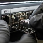
Commissioning best practice is to validate in a controlled environment. In a lab or staging rack, plug the candidate MINI-LINK SFP into the exact chassis model, connect to a known-good optical attenuator or loopback, and verify DOM readings (Tx power, Rx power, and temperature). If the chassis logs an alarm for DOM mismatch, you want to know that before someone climbs a ladder.

Deployment scenario: MINI-LINK SFP swap on a leaf-spine transport edge
Consider a 3-tier data center edge where a microwave backhaul aggregates traffic into a transport switch stack. In one real-style scenario: 48-port 10G ToR switches uplink to a pair of spine switches over 10G Ethernet, and the backhaul enters through two redundant microwave radios. The optical handoff uses SFP optics at 10.3125 Gb/s into LC fiber, with a mix of short patch runs inside the rack and longer SMF segments to an aggregation hut.
The team plans a maintenance window to replace failing optics on the backhaul side. They identify that the original modules were configured as 10G LR (1310 nm) but a migration attempt accidentally stocked SR-style modules for a different path. The result was no stable link: the receivers saw out-of-spec optical power, and DOM values failed to converge. After swapping to the correct LR-compatible MINI-LINK SFP type and cleaning both LC ends with a proper inspection scope, Rx power settled within the chassis’ acceptable threshold and packet loss dropped to baseline.
Operationally, the team also used temperature-aware monitoring. On the hut side, ambient conditions reached 45 C during peak sun. By selecting an industrial-temperature optic and verifying DOM temperature stability, they avoided intermittent CRC errors that had appeared during the hottest hours.
Common mistakes and troubleshooting that actually works
Even smart teams get burned by the same failure modes. Here are concrete pitfalls engineers hit when working with MINI-LINK SFP optics in Ericsson-style microwave transport environments.
Reach mismatch: SR optics on a longer SMF plan
Root cause: The module’s wavelength and reach target do not match the fiber path assumptions. SR modules (850 nm) are for short MMF distances; using them where the plan expects SMF LR/ER will cause weak or absent receive power.
Solution: Verify fiber type and planned wavelength at both ends. Use a known-good optical power meter reading and compare against module datasheet typical receive sensitivity. Replace with the correct wavelength class (e.g., 1310 nm LR for SMF).
DOM alarm or silent incompatibility
Root cause: Some chassis enforce DOM behavior. A third-party optic may present different DOM fields, or the chassis may treat missing thresholds as a fault even if the link “comes up.”
Solution: Confirm DOM compatibility in staging. Check chassis logs immediately after insertion, and validate that DOM values populate and remain within expected ranges over a temperature cycle.
Dirty LC connectors pretending to be “bad optics”
Root cause: Contaminated fiber end faces can create high insertion loss and intermittent link flaps. The optics can be perfect, but the light never makes it through cleanly.
Solution: Always inspect with a fiber scope before condemning a module. Clean with lint-free methods and re-check end-face condition. After cleaning, re-measure Rx power and monitor for link stability across 30 to 60 minutes.
Temperature drift and marginal optical budget
Root cause: A module that barely meets budget may work in the morning and fail at midday when thermal conditions change. This often shows up as rising CRC or FEC errors.
Solution: Choose industrial-temperature optics and ensure link margin. If possible, reduce path loss by shortening patch segments, improving splices, or upgrading to higher-budget optics.
Cost and ROI note: where the money actually goes
Optics pricing varies wildly by brand, temperature grade, and whether the module is OEM-locked. In many markets, a 10G SR optic might cost roughly $40 to $120 for third-party and $120 to $250 for OEM-grade modules, while LR/ER variants can be higher. The real ROI is not the sticker price; it is commissioning time, failure rate, and downtime costs.
TCO drivers for MINI-LINK SFP deployments typically include labor for swaps, truck rolls, and incident response. If third-party optics reduce purchase cost but increase field failures, your “savings” evaporate faster than a microwave link during heavy rain. A practical approach is to buy a larger batch of the selected compatible type only after at least one successful staging test and a short pilot in the target environment.
Power savings are usually minor compared to cooling and baseband consumption, but monitoring-enabled optics (DOM) can reduce time-to-diagnosis. That operational efficiency often beats small unit cost differences.
FAQ: MINI-LINK SFP buying questions from people who have been burned
What does MINI-LINK SFP compatibility mean for an Ericsson microwave chassis?
It means the transceiver must match the chassis expectations for data rate, wavelength, and often DOM monitoring behavior. Check the platform’s transceiver guidance and verify in staging that DOM fields populate without alarms. A link that “comes up” is not the same as a link that will stay stable under temperature cycling.
Can I use third-party MINI-LINK SFP modules instead of OEM optics?
Often yes, but only if the optics meet the required optical parameters and are compatible with the chassis’ DOM behavior. Plan a pilot using the exact chassis model and fiber path characteristics, then monitor DOM and error counters for at least 24 hours. If the chassis logs module-related faults, do not proceed to live deployments.
How do I choose between 850 nm and 1310 nm MINI-LINK SFP optics?
Choose based on fiber type and planned reach. 850 nm typically targets short-reach multimode (MMF), while 1310 nm is commonly used for longer-reach single-mode (SMF) links. Confirm the remote end wavelength too, because mismatched wavelength pairs will fail regardless of connector shape.
What DOM metrics should I watch after installing a MINI-LINK SFP?
Focus on transmit power, receive power, and module temperature. Compare readings to the typical ranges in the module datasheet and watch for drift over time. If Rx power is near the sensitivity edge, you will see intermittent errors that correlate with thermal conditions.
Why does my link flap after a MINI-LINK SFP replacement?
Common causes include dirty LC connectors, reach mismatch, or marginal optical budget exposed by temperature changes. Inspect and clean connectors, verify wavelength and fiber type, and check chassis alarms and error counters. If DOM values are unstable, the module may be incompatible or failing under environmental stress.
What should I include in a spares strategy for MINI-LINK SFP optics?
Keep spares by wavelength class, data rate, and temperature grade aligned to the actual deployed paths. Include at least one known-good module for each required class and validate them with a staging checklist before storing. Also track which modules are used on which fiber segments so you do not repeat the classic “wrong optics for the wrong path” incident.
Choosing the right MINI-LINK SFP is a strategy problem disguised as a hardware purchase: match wavelength and reach, validate DOM compatibility, and protect link margin with connector hygiene and temperature-aware optics. Next step: review your Ericsson transceiver guidance and align your inventory using the checklist above via fiber optic transceiver selection checklist.
Sources: [Source: IEEE 802.3 Ethernet PHY specifications] [Source: Vendor SFP transceiver datasheets for optical parameters and DOM behavior] [Source: Ericsson microwave transceiver guidance and platform documentation] [Source: ANSI/TIA-568 and related fiber cabling practices for installation quality].
Author bio: I have deployed and replaced SFP optics in live microwave and data center transport environments, validating link budgets with DOM readings and error counters. I write to help teams reduce downtime and avoid paying for “learning experiences” at tower-site rates.