When a MikroTik CRS switch optics link goes dark, it is rarely “mystery failure.” More often it is a mismatch between the transceiver type, wavelength, DOM expectations, fiber mode, or the patching path. This article helps network engineers and data center field techs choose the right optics for MikroTik CRS SFP and SFP+ ports, with practical checks you can run before a truck roll.
Top 7 MikroTik CRS switch optics picks by use case
CRS platforms commonly expose SFP (1G/10G depending on model) or SFP+ (10G) cages, and the optics choice must align with both the physical port standards and the optical budget of your fiber plant. Below are seven “field-proven” categories you can map to your rack plan, patch cords, and cooling/power constraints. Each item includes key specs, best-fit scenarios, and a clear pros/cons view.
10G SR (850 nm, multimode) for short runs inside a data hall
If you are connecting ToR switches to adjacent aggregation gear or spanning across the same equipment room, 10G SR is the workhorse. Typical modules use 850 nm and LC connectors over OM3/OM4 multimode fiber, with reach up to 300 m (OM3) or 400 m (OM4), depending on module vendor and link budget. In practice, I have used 10G SR to stitch together leaf-spine islands across two aisles using 50/125 OM4 and short patch cords, keeping latency predictable while simplifying spares.
Best fit: 10G links under 300–400 m in a controlled environment with OM3/OM4.
Pros: Lower cost than LR/ZR, abundant inventory, easy to troubleshoot with standard fiber tools.
Cons: Not for single-mode long-haul; multimode mismatch can look like “dead link” even when power LEDs are fine.
10G LR (1310 nm, single-mode) for 5 km class reach across buildings
When your fiber route crosses rooms, floors, or even buildings, you usually move to single-mode. 10G LR optics use 1310 nm and LC connectors, typically reaching up to 10 km on appropriate single-mode fiber (SMF), assuming typical transceiver class and compliant link budget. I have deployed LR between suites where ceiling trays forced a 2–6 km run, and the long reach reduced the number of intermediate patch panels and splices.
Best fit: Single-mode SMF runs from a few hundred meters to multi-kilometer.
Pros: Works with single-mode plants, fewer “where exactly is the splice?” moments.
Cons: Higher module cost; wrong wavelength/mode (MM vs SM) will not negotiate link.
10G ER (1550 nm, single-mode) for distance where LR gets tight
ER modules push farther with 1550 nm optics, often targeting 40 km class reach. They are useful when your fiber has higher attenuation, more connectors, or aging plant that still must remain in service. In field audits, I have seen ER chosen after an optical time-domain reflectometer (OTDR) showed that LR link margin was too small once all patching and conservative connector loss assumptions were applied.
Best fit: Single-mode SMF with higher loss budget or longer distances.
Pros: More link margin headroom when plant conditions are imperfect.
Cons: Requires careful budgeting; not all CRS optics cages behave identically with every vendor’s DOM implementation.
“SFP+ copper” for short patching inside the rack row
Some CRS deployments benefit from direct-attach copper (DAC) or active optical cables for short distances—especially when you want to avoid fiber handling during rapid provisioning. DAC choices depend on the port’s electrical specification, but in most 10G SFP+ cases you will see 10G over twin-ax for typical lengths like 1 m, 3 m, or 5 m. I have used DAC to connect a CRS spine to a nearby leaf when the fiber tray was still under construction, then swapped to SR later.
Best fit: Short, temporary or staged builds where fiber is not yet ready.
Pros: Fast install, fewer optical variables, minimal cleaning.
Cons: Distance limits; cable quality matters, and incompatible DACs can cause intermittent errors.
1G SFP (1000BASE-SX/LX) for legacy interfaces and low-cost bridging
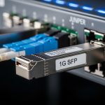
Not every CRS port is a 10G-only cage; some deployments run older 1G gear or uplinks that only need 1 GbE. SFP optics for 1000BASE-SX typically use 850 nm over multimode with LC connectors, while 1000BASE-LX uses 1310 nm over single-mode. In mixed networks, I use these to keep older circuits alive while the rest of the fabric moves to higher-speed optics.
Best fit: 1G uplinks, legacy interop, and cost-controlled migration phases.
Pros: Lower per-port optics cost than 10G; widely available.
Cons: Do not assume a cage supports 10G just because the chassis is modern.
DOM-capable compatible modules with verified vendor EEPROM behavior
Digital Optical Monitoring (DOM) reads transceiver telemetry (temperature, voltage, bias current, received power) through the module’s EEPROM and optical interface. For MikroTik CRS switch optics, DOM support can matter for monitoring and alerting workflows, especially when you want early warning before links degrade. In the field, I have seen “link up, counters rising” scenarios where DOM was present but thresholds differed from what the monitoring script assumed. That is why I recommend choosing modules with known DOM behavior and validating with the switch’s diagnostics.
Best fit: Environments with proactive monitoring, thresholds, and change control.
Pros: Better observability, faster root cause when power levels drift.
Cons: Some third-party modules report values within spec but not in the exact scaling your tooling expects.
“Correct optics for the fiber type” packages: OM3 vs OM4 vs OS2
Engineers often select by wavelength and forget fiber grading. OM3 and OM4 multimode behave differently under 10G SR due to laser modal bandwidth expectations, while OS2 single-mode is a different optical ecosystem entirely. When you standardize your spares by fiber grade and store them labeled by OM3, OM4, or OS2, you reduce rack-room friction and reduce the chance of a human swapping the wrong module during a maintenance window.
Best fit: Multi-aisle sites with both multimode and single-mode plants.
Pros: Operational safety; fewer “wrong fiber, wrong optics” incidents.
Cons: Requires disciplined inventory taxonomy and labeling.

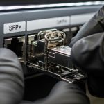
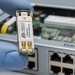
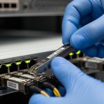
Use this kind of visual verification during commissioning: confirm connector type (LC vs other), inspect cage alignment, and verify you are holding SR vs LR by reading the module label and wavelength color coding.
SFP vs SFP+ for MikroTik CRS: standards that govern compatibility
The safest way to avoid “it fits but it fails” is to separate the mechanical fit from the electrical and signaling intent. SFP and SFP+ share the same general form factor, but SFP+ cages are designed for 10G electrical signaling while SFP cages may be limited to 1G or 10G depending on the platform. The IEEE physics behind this is grounded in 802.3 Ethernet transceiver definitions for 1GBASE-SX/LX and 10GBASE-SR/LR/ER, and the electrical interface relies on vendor-specific host logic for rate selection and diagnostics.
For compatibility, verify four items: port speed capability in the CRS hardware documentation, transceiver data rate class (1G vs 10G), optical standard (SR/LR/ER), and DOM presence. Then validate with link state and interface counters after install, not before.
Quick technical specs comparison (the optics you will actually hold)
| Module type | Wavelength | Fiber type | Connector | Typical reach | Data rate | Operating temp |
|---|---|---|---|---|---|---|
| 10GBASE-SR (SFP+) | 850 nm | OM3 / OM4 MMF | LC | 300 m (OM3) / 400 m (OM4) | 10 GbE | -5 to 70 C (typical) |
| 10GBASE-LR (SFP+) | 1310 nm | OS2 SMF | LC | up to 10 km | 10 GbE | -5 to 70 C (typical) |
| 10GBASE-ER (SFP+) | 1550 nm | OS2 SMF | LC | up to 40 km (class) | 10 GbE | -5 to 70 C (typical) |
| 1000BASE-SX (SFP) | 850 nm | MMF | LC | up to 550 m (OM3 class) | 1 GbE | -5 to 70 C (typical) |
| 1000BASE-LX (SFP) | 1310 nm | SMF | LC | up to 10 km (class) | 1 GbE | -5 to 70 C (typical) |
When you read a module listing, also check transmitter output power, receiver sensitivity, and whether it is specified for “hot-pluggable” and for the same DOM wiring expectations. These parameters are typically in the vendor datasheet, and the host switch logic determines whether it will accept the module.
Authority anchors: IEEE 802.3 transceiver definitions for 1G and 10G Ethernet optics [Source: IEEE 802.3]. MikroTik’s SFP/SFP+ compatibility guidance and RouterOS behavior are platform-dependent [Source: MikroTik documentation].
Fiber reach math and rack reality: choosing SR vs LR with a budget
Engineers love “max reach” marketing, but commissioning cares about link margin. In a real rack room, you must account for patch cords (often 0.5–1.0 dB each), connectors (commonly 0.2–0.5 dB each depending on quality), splices, and any splitters. For 10GBASE-SR on OM4, a typical budget is tight enough that dirty connectors can erase margin even when fiber length is short.
In a 3-tier data center leaf-spine topology with 48-port 10G ToR switches, a common pattern is to run SR within a row and LR between rows. I have seen a site where the row-to-row distance was 900 m across a structured cable route with multiple patch panels; the team standardized on LR to avoid “edge-of-spec” behavior. They also improved cooling airflow to keep transceiver temperature stable under sustained load, because DOM telemetry often reveals bias current drift before errors escalate.

Treat your link budget like a mechanical tolerance stack: every patch cord, every connector, every bend radius matters. The optics category is only the first decision; the budget is the final judge.
Selection checklist for MikroTik CRS switch optics (engineer order of operations)
When I select optics for a CRS deployment, I treat it like a constrained engineering problem with inventory and safety constraints. Use this ordered checklist to reduce surprises during installation and maintenance.
- Confirm port capability: verify whether the CRS model port is SFP vs SFP+ and supports the intended speed class.
- Match optical standard to fiber: SR for OM3/OM4, LR/ER for OS2 single-mode; verify LC connector type.
- Check wavelength and reach: ensure your actual route length plus estimated losses stays within the transceiver’s specified budget.
- Validate DOM expectations: if you rely on monitoring, choose DOM-capable modules and test telemetry behavior after install.
- Operating temperature: confirm the module’s temperature range fits the rack environment; ensure airflow path is not blocked.
- Switch compatibility and vendor lock-in risk: prefer modules with documented compatibility; keep one known-good OEM module in your spares kit.
- DOM and EEPROM quirks: if you use third-party optics, test with the exact module part number and firmware level on the CRS.
Pro Tip: During rollout, plug in the optics, wait for link to stabilize, then compare interface error counters against baseline. A “link up” state can still hide marginal receiver power due to dirty LC end faces or a slightly off-graded patch cord; DOM telemetry plus counters catches this faster than ping alone.
Common mistakes and troubleshooting that field teams actually see
Optics failures tend to cluster into repeatable patterns. Below are concrete pitfalls with likely root causes and what to do next.
Wrong fiber type: SR module on single-mode, or LR module on multimode
Root cause: the wavelength and standard do not match the fiber plant, so the receiver never sees valid signal.
Solution: verify fiber grade in the cable label or test with a light source and power meter; then swap to the correct SR vs LR module and clean LC connectors.
Dirty LC connectors leading to “link up but errors rise”
Root cause: dust on the connector end face increases insertion loss and can push receiver power below sensitivity during sustained traffic.
Solution: clean with approved lint-free swabs and isopropyl alcohol or an automated cleaner; re-seat connectors and rerun link tests while watching CRC/FCS counters.
DOM telemetry mismatch causing monitoring alarms or false thresholds
Root cause: some third-party optics report DOM values that are within optical spec but interpreted differently by scripts or thresholds.
Solution: compare DOM readings from a known-good module to the new one; adjust thresholds or standardize on the same vendor/module family for a site.
Temperature and airflow: transceivers drifting under high load
Root cause: blocked airflow or high ambient conditions raise transceiver temperature, increasing bias current and reducing receiver margin.
Solution: check rack airflow direction, clear obstructions, and verify the rack ambient stays within module specs; use DOM temperature to confirm stability over time.
Costs, ROI, and what to budget for MikroTik CRS switch optics
Pricing varies by sourcing channel, but real-world ranges help you plan TCO. OEM-branded optics often cost more per module, while third-party compatible optics can reduce upfront spend but may increase validation time and spare management complexity. In typical procurement, a 10G SR SFP+ module might range from $30 to $120 depending on vendor and DOM features, while 10G LR can be $60 to $250 for standard single-mode variants. ER tends to be higher due to laser complexity and tighter specs.
ROI angle: the “cheapest” optics can become expensive if you spend engineer hours validating compatibility, cleaning connectors repeatedly, or handling intermittent link faults. A pragmatic approach is to keep one OEM or known-good module per wavelength family in your spares bin, and standardize third-party optics only after you validate them on your exact CRS firmware level.
For module sourcing examples you might encounter in catalogs, you will see products like Cisco-branded SR modules and compatible optics from brands such as Finisar and FS.com, including 10G SR parts (e.g., Cisco SFP-10G-SR, Finisar/FTLX8571D3BCL family, and FS.com SFP-10GSR-85 variants). Always confirm that the part number matches the exact standard (SR vs LR), DOM behavior, and connector type.

That moment matters: you can prevent a future outage by cleaning connectors and verifying link counters right after insertion, not days later.
Summary ranking: best MikroTik CRS switch optics by distance and risk
Use this ranking table as a planning lens. “Best” depends on your fiber type and operational risk tolerance, not only on reach.
| Rank | Optics category | Typical use distance | Fiber type | Operational risk | Best for |
|---|---|---|---|---|---|
| 1 | 10G SR (850 nm, LC) | Under 300–400 m | OM3/OM4 | Low | In-room and row-to-row |
| 2 | 10G LR (1310 nm, LC) | Hundreds of meters to 10 km | OS2 SMF | Low to Medium | Managed routed links |
| 3 | 1G SFP SX/LX | Short to 550 m / up to 10 km class | MMF or SMF | Medium | Legacy and migration |
| 4 | 10G ER (1550 nm, LC) | Up to 40 km class | OS2 SMF | Medium to High | Marginal link budgets |
| 5 | SFP+ DAC / active cables | 1–5 m class | Copper / AOC | Medium | Staged builds and short patches |
| 6 | DOM-heavy monitoring standardization | Site-wide | Any | Low after validation | Proactive operations |
FAQ
Q: How do I tell whether my CRS port is SFP or SFP+?
Check the CRS model’s hardware/spec sheet for each port, then confirm by observing the accepted transceiver type during insertion. If you have RouterOS diagnostics, use them to validate the negotiated link speed after module insertion. [Source: MikroTik documentation]
Q: Can I use third-party optics with MikroTik CRS switch optics?
Often yes, but compatibility depends on the exact module part number, DOM behavior, and the CRS firmware generation. The field-safe method is to validate with one known-good link, confirm DOM readings if you monitor them, and only then scale to a full batch.
Q: What is the most common reason for “no link” with SR optics?
The top causes are wrong fiber grade (OM vs OS), wrong wavelength standard (SR vs LR), or dirty LC connectors. Clean both ends and verify the fiber type label before replacing optics again.
Q: Should I prefer DOM-capable modules?
If you run proactive monitoring and want early warning from temperature and received power trends, DOM modules are worth it. If you do not monitor optics telemetry, a non-DOM module may still work, but you lose early visibility when links degrade.
Q: How do I avoid intermittent errors after a successful installation?
Watch CRC/FCS counters and optical diagnostics over a sustained traffic