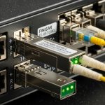
Edge deployments often connect small compute sites into a larger routing fabric, and the weakest link is frequently optical reach, connector cleanliness, and SFP compatibility. This guide helps network engineers and field technicians select the right SFP transceivers for micro data center fiber runs in distributed compute environments. You will get a step-by-step implementation flow, a troubleshooting section with root causes, and a practical checklist you can apply on site.
Prerequisites: what to measure before you pick an SFP
Before purchasing optics, capture the real physical and control-plane constraints. In edge sites, the most expensive mistake is selecting an SFP that works on your bench but fails in the field due to link budget margin, temperature derating, or switch DOM expectations. Plan to verify fiber type, end-to-end distance, and whether your switch supports the specific transceiver vendor or EEPROM profile.
Inventory the edge link endpoints
Write down the exact switch model and the port type (SFP, SFP+), along with speed requirements (for example, 10G or 25G). Confirm whether your fabric uses VLANs and whether the uplink is trunked or access. For distributed compute, it is common to carry a management VLAN plus one or more tenant VLANs, so you need predictable L2 behavior during optical upgrades.
Expected outcome: A list of ports, target data rate, and whether you need single-mode or multi-mode.
Measure distance and fiber plant characteristics
Use an optical time-domain reflectometer (OTDR) or a reliable certified tester to measure end-to-end length and identify splice loss. If you do not have OTDR data, at least verify the fiber type label and connector style at both ends. For short runs inside cabinets, multi-mode can work; for longer “edge to aggregation” spans, single-mode is typically required.
Expected outcome: A distance number plus a conservative loss estimate (include patch cords, adapters, and splices).
Confirm link budget margin for your target optics
Every SFP has a transmit power and receiver sensitivity that define allowable loss. In practice, you should budget for connector contamination and aging, not just the nominal spec. A common field rule is to keep at least 3 to 6 dB of margin beyond the calculated loss, especially in micro data center fiber bundles that get moved during maintenance.
Expected outcome: A go/no-go assessment that your planned wavelength and reach can survive real losses.

SFP selection for micro data center fiber: wavelength, reach, and DOM
The core choice is not “SFP or not SFP,” it is which optical profile matches your link budget and your switch’s transceiver policy. For micro data center fiber in distributed compute, engineers often standardize on one or two optics families to reduce operational risk and spare complexity. Still, you must account for duplex, wavelength, and whether the switch requires a specific DOM format.
Pick the data rate and the SFP form factor
Most edge compute deployments use SFP+ (10G) or SFP28 (25G), depending on server NIC capability and aggregation bandwidth. If your switch supports only SFP+ on a given port, do not assume an SFP28 module will negotiate correctly. Verify the port speed matrix in the vendor datasheet before you open a box.
Choose single-mode vs multi-mode based on distance
For micro data center fiber runs under a few hundred meters inside a room, multi-mode can be cost-effective. For longer spans between cabinets, buildings, or remote aggregation points, single-mode is usually the reliable choice. If you are unsure, run a quick test: if the fiber is labeled “OM3” or “OM4,” you can plan for 850 nm optics; if it is “OS2,” plan for 1310 nm or 1550 nm optics.
Select wavelength and connector type that match the plant
Common mappings are: 850 nm for multi-mode (short reach), 1310 nm for single-mode lower-cost optics, and 1550 nm for longer reach. Also confirm connector type: LC is dominant in modern SFP deployments, but you may encounter SC in legacy fiber panels. Use matched adapters and keep a strict cleanliness workflow on every patch.
Verify DOM support and switch compatibility
Digital Optical Monitoring (DOM) lets the switch read temperature, laser bias, and receive power. Many switches accept “vendor-agnostic” optics, but some enforce compatibility lists or require DOM behavior that matches the expected EEPROM layout. When you standardize, buy enough spares of the same model number to avoid cross-vendor surprises during maintenance windows.
Technical specifications comparison (common edge optics)
Below is a practical comparison of widely deployed SFP module families used with micro data center fiber in edge environments. Exact values vary by vendor, but the trends are stable: wavelength determines fiber type, reach determines link budget, and DOM support affects operational visibility.
| Module type | Typical wavelength | Target reach | Connector | Data rate | DOM | Operating temp | Example part numbers |
|---|---|---|---|---|---|---|---|
| SFP+ 10G SR | 850 nm | Up to 300 m (OM3) / 400 m (OM4) | LC | 10G | Usually yes | 0 to 70 C (typical) | Cisco SFP-10G-SR, Finisar FTLX8571D3BCL, FS.com SFP-10GSR-85 |
| SFP+ 10G LR | 1310 nm | Up to 10 km | LC | 10G | Usually yes | -5 to 70 C (typical) | Juniper/compatible 10G-LR families, generic OS2 1310 nm SFP+ LR |
| SFP28 25G SR | 850 nm | Up to 70 m (OM3) / 100 m (OM4) | LC | 25G | Usually yes | 0 to 70 C (typical) | 25G SR SFP28 module families (OM4 LC) |
| SFP28 25G LR | 1310 nm | Up to 10 km | LC | 25G | Usually yes | -5 to 70 C (typical) | 25G LR SFP28 OS2 1310 nm modules |
Implementation steps: build the edge link and validate L2 behavior
Once optics are selected, you need a controlled install and validation sequence. Edge sites frequently experience intermittent issues that only appear under load, so validation must include both optics layer health and VLAN forwarding behavior. Keep a rollback plan in case the switch rejects the module or the link negotiates at an unexpected speed.
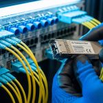
Clean and terminate connectors before insertion
Connector cleanliness is the most common reason for “it works on the bench, fails in the rack” events. Use fiber inspection with a microscope and clean with approved isopropyl and lint-free wipes only when the manufacturer allows it; otherwise use dedicated cleaning tools and caps. Ensure LC end faces are free of scratches and residue before you insert the SFP.
Expected outcome: Reduced receive power penalties and fewer marginal link flaps.
Insert optics and verify link negotiation
Power the switch normally, insert the SFP carefully, and watch interface state changes. On Cisco-like CLI, you typically check something like interface counters and transceiver diagnostics; on many platforms you can view DOM readings and alarm flags. If the switch reports “unsupported transceiver,” stop and check compatibility policy rather than repeatedly reseating.
Expected outcome: Interface comes up at the intended speed with stable link indicators.
Validate VLAN trunking and forwarding under traffic
In micro data center fiber deployments, you often run a management VLAN plus tenant VLANs across the same uplink. Verify that the port is configured as trunk if required, with the correct allowed VLAN list. Then generate controlled traffic (for example, iperf3 between edge compute nodes and the aggregation switch) to confirm that VLAN forwarding is stable and that no unexpected MTU issues exist.
Expected outcome: VLANs pass traffic with no drops, and counters remain stable under load.
Pro Tip: DOM “present” is not the same as “healthy.” In the field, I have seen optics report readable DOM but still run near the receiver threshold; a quick comparison of receive power readings before and after a connector cleaning event often reveals whether the problem is optics aging or fiber contamination.

Selection criteria and decision checklist for edge distributed compute
Use the ordered checklist below to select micro data center fiber optics that will survive real edge conditions. This approach reduces rework when you are juggling multiple sites and limited maintenance windows.
- Distance and fiber type: OS2 vs OM3/OM4 labels, plus measured loss (include patch cords and splices).
- Target speed and port support: ensure SFP+ vs SFP28 matches switch port capability.
- Wavelength fit: 850 nm for OM multi-mode, 1310 nm for OS2 single-mode in most edge cases.
- Connector and adapter plan: LC vs SC, APC vs UPC if applicable, and proper cleaning workflow.
- DOM and alarms: confirm switch reads DOM correctly and supports transceiver diagnostics.
- Operating temperature: verify module grade for the cabinet environment; check vendor spec.
- Budget and spare strategy: consider buying matched spare pairs and standardizing module models across sites.
- Vendor lock-in risk: if you use OEM-only optics, model TCO and warranty replacement lead times.
Common mistakes and troubleshooting: top failure modes
Below are the most frequent edge deployment failures tied to micro data center fiber and SFP selection. Each item includes likely root cause and a practical fix you can execute during a field visit.
Failure point 1: Link flaps or never comes up after insertion
Root cause: connector contamination, wrong polarity, or exceeding link budget due to unaccounted patch cord loss. In edge sites, technicians sometimes reuse older patch cords with degraded end faces.
Solution: inspect both ends with a fiber microscope, clean with approved tools, and verify transmit/receive polarity. Re-test with an optical power meter if available, and compare receive power against the module’s expected range.
Failure point 2: Switch shows “unsupported transceiver” or drops to low speed
Root cause: EEPROM/DOM compatibility mismatch or switch transceiver policy rejecting third-party modules. Some platforms enforce vendor-specific identification strings.
Solution: check the switch vendor compatibility matrix and try an approved module model number. If the platform supports “transceiver type” overrides, validate the configuration method from the vendor documentation before changing it broadly.
Failure point 3: Interfaces pass light traffic but fail under load
Root cause: marginal optical signal, micro-bending in fiber trays, or an unbalanced cleaning history that only fails at higher BER. Sometimes the fiber path includes a tight bend radius that is acceptable for short runs but not stable under thermal cycling.
Solution: verify bend radius compliance in the fiber management system and re-route if needed. Re-check DOM receive power and error counters during traffic bursts; if errors rise quickly, treat it as a physical-layer issue first.
Cost and ROI note: OEM optics vs third-party for edge sites
In micro data center fiber deployments, optics cost is only part of the TCO. OEM SFP modules often cost more, but they reduce compatibility friction and can simplify RMA workflows. Third-party modules can be viable when they are properly validated, but you should account for higher failure variability and longer qualification cycles across multiple switches and sites.
Typical price ranges: 10G SR SFP+ modules often fall in a mid-range per-unit cost band depending on brand and DOM support; 10G LR and 25G modules are usually more expensive due to optics and qualification. For ROI, factor in truck rolls, outage risk, and spare inventory carrying costs; in distributed compute, downtime frequently costs more than the optics price difference.
FAQ
What fiber type should I use for micro data center fiber at an edge site?
Use multi-mode (OM3/OM4) for short in-room cabinet runs and single-mode (OS2) for longer spans between racks, rooms, or buildings. If you are unsure, verify fiber labeling and measure loss with OTDR or certified test results before selecting 850 nm versus 1310 nm optics.
How do I confirm an SFP module will work with my switch?
Check the switch vendor’s compatibility list and confirm the exact port speed (SFP+ vs SFP28). Also verify DOM behavior: the switch should read transceiver diagnostics without “unsupported” errors.
Can I mix optics vendors across different edge sites?
You can, but it increases operational variability during troubleshooting. In practice, standardize on a small set of SFP model numbers per platform so your maintenance team can predict DOM readings and alarm thresholds consistently.
What is the most common cause of optical link issues in the field?
Connector contamination and improper cleaning are the most frequent causes of marginal links and flaps. Always inspect fiber end faces, clean with approved tools, and verify polarity before swapping optics.
Do DOM readings replace link testing?
No. DOM helps you see trends like temperature and receive power, but you still need counters and BER/error monitoring under traffic. Treat DOM as a diagnostic aid, not a substitute for physical-layer validation.
How much link budget margin should I keep?
As a starting point, keep at least 3 to 6 dB beyond your calculated end-to-end loss, especially in environments where fibers move during maintenance. If your cabinet temperatures are high or the fiber plant is older, bias toward more margin.
With measured loss, correct wavelength selection, and a validated DOM and VLAN plan, micro data center fiber links become predictable even across many edge sites. For related routing and VLAN validation in distributed deployments, see edge VLAN design for distributed compute.
Author bio: Veteran network admin specializing in fiber optics, VLAN transport, and edge routing validation across multi-vendor switching. Field experience includes commissioning distributed compute sites with OTDR-based acceptance testing and SFP compatibility qualification.