Metro access SFP modules often sit at the boundary between carrier-grade Ethernet and customer premises equipment (CPE). This article helps network engineers and field technicians choose the right `metro access SFP` for EFM and NID designs, with an emphasis on operational safety, compatibility, and testable specs. You will get a head-to-head comparison of common 1G and 10G optics, a decision checklist, and practical troubleshooting patterns seen in live installs.
Metro access SFP: EFM and NID roles, and why optics selection matters
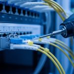
In EFM (Ethernet in the First Mile) and NID (Network Interface Device) deployments, the transceiver is the physical layer gatekeeper for link stability, reach, and fault isolation. EFM requirements are typically tied to Ethernet physical layer behavior and deterministic performance expectations over access distances; NIDs then translate that into customer-facing service handoffs. In practice, your optical budget, fiber type (single-mode vs multi-mode), and connector cleanliness determine whether the link trains reliably after maintenance windows.
From an engineering perspective, “metro access SFP” usually means an SFP-class optical transceiver used in access/aggregation spans, often with single-mode reach targets (for example, 10GBASE-LR style links) or short single-fiber or multi-fiber runs depending on the plant. Standards guidance for Ethernet physical layer behavior is anchored in IEEE 802.3 family documents, while module electrical and optical characteristics come from SFP/SFP+ specifications and vendor datasheets. See [Source: IEEE 802.3] and [Source: IEEE 802.3 Clause references in vendor application notes].
Operationally, the SFP must match both the switch’s optical expectations and the plant’s fiber plant constraints. Mismatched optics (wrong wavelength band, wrong fiber type, wrong duplex mapping) can produce intermittent link flaps that are costly to debug. If you run a remote NID, you also need predictable behavior under temperature swings and realistic aging.
Head-to-head: 1G vs 10G metro access SFP optics for EFM and NID
Below is a practical comparison of the optics families most frequently considered for metro access SFP use in access and NID contexts. The goal is not “best at any distance,” but “best match for your reach, budget, and compatibility constraints.” For each option, verify that your switch supports the exact wavelength and transceiver class, and confirm DOM behavior if your network uses telemetry.
| Option (Typical) | Data rate | Wavelength | Reach class | Fiber / connector | Power class (typ.) | DOM | Operating temp (typ.) |
|---|---|---|---|---|---|---|---|
| 1GBASE-BX (single fiber) | 1.25G | 1310/1490 nm (varies by direction) | Up to ~10 km (SMF) | Single-mode, LC | ~1 W class | Common | 0 to 70 C (commercial) or -40 to 85 C (extended) |
| 1GBASE-LX (1310 nm) | 1.25G | 1310 nm | Up to ~10 km (SMF) | Single-mode, LC | ~1 W class | Common | 0 to 70 C or -40 to 85 C |
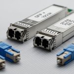
| 10GBASE-LR (metro access SFP+ style) | 10.3125G | 1310 nm | Up to ~10 km (SMF) | Single-mode, LC | ~1.5 to 2.5 W class | Common | 0 to 70 C or -40 to 85 C |
| 10GBASE-SR (short reach) | 10.3125G | 850 nm | Up to ~300 m (MMF, varies) | Multi-mode, LC | ~1.5 to 2.5 W class | Common | 0 to 70 C |
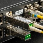
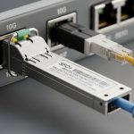
Typical vendor part families to look for include 10G LR optics sold as 10G SFP+ (for example, Cisco SFP-10G-SR is SR at 850 nm, while LR models vary by vendor) and compatible optics from manufacturers such as Finisar and FS.com. When you evaluate, treat “reach” as a budget statement that assumes standard fiber types, connector loss, and conservative margins. Always validate against your specific fiber attenuation and splice/patch loss records.
Pro Tip: In field troubleshooting, the fastest path is to compare DOM-reported transmit power and receive power against your expected optical budget margins. Even when link LED states “up,” a slowly degrading receive margin can predict the next outage after a connector cleaning or a seasonal temperature shift. DOM data is often the earliest signal before total link failure.

Compatibility and safety: switch support, DOM telemetry, and optical budget
Compatibility is the number one differentiator between “works in the lab” and “works after dispatch.” First, confirm that your switch model and software release support third-party optics, and that the vendor’s compatibility matrix includes your exact transceiver class. Second, verify DOM support: many NIDs and monitoring stacks rely on DDM/DOM alarms for laser bias current, temperature, and optical power thresholds.
Optical budget math is not optional for metro access SFP planning. Use your fiber attenuation (dB/km), estimated splice and patch loss (dB each), and connector insertion loss, then compare to the module’s published transmit power and receiver sensitivity. If you are using a single-fiber BX-style link, confirm direction pairing (for example, 1310 transmit on one end and 1490 transmit on the other) and ensure your plant patching matches that expectation.
Safety-wise, treat SFP optics as Class 1 laser products in normal operation, but still follow laser safety practices during inspection. Never stare into an optical port; use approved inspection tools and keep dust caps on when fibers are disconnected. Reference module safety and regulatory context in vendor documentation and general laser safety guidance from credible authorities such as [Source: FDA laser safety guidance] and vendor datasheets.
Decision checklist: how engineers pick the right metro access SFP
Use this ordered checklist during design or procurement to reduce returns and truck rolls. It is written for real EFM and NID workflows where fiber records can be incomplete and maintenance windows are short.
- Distance and fiber type: measure or confirm SMF vs MMF, and verify attenuation and splice counts.
- Reach class vs optical budget: compare published reach to your budget with margin; do not assume “max reach” is stable for your exact plant.
- Switch compatibility: check the exact switch model’s transceiver compatibility list and software version.
- DOM/telemetry requirements: confirm DDM/DOM support and whether your monitoring system expects alarm thresholds.
- Operating temperature: for outdoor NIDs or cabinets, prefer extended temperature (-40 to 85 C) when available and justified.
- Connector and polarity: LC type, duplex mapping, and for BX links, direction pairing and patch cord orientation.
- Vendor lock-in risk: evaluate OEM-only policies vs third-party validated options; plan for spares strategy.

Common pitfalls and troubleshooting patterns (with root cause and fixes)
Even experienced teams see repeat failure modes. Below are concrete pitfalls that map to typical EFM and NID environments, with root causes and targeted solutions.
-
Pitfall 1: Link flaps after a maintenance event
Root cause: connector contamination or micro-scratches on LC endfaces after a fiber is reseated.
Solution: clean with lint-free wipes and approved fiber cleaning tools; verify with an optical microscope/inspection scope before re-terminating; standardize cleaning steps across shifts. -
Pitfall 2: “Up” but high errors or intermittent CRC bursts
Root cause: insufficient optical margin due to unexpected splice loss, aging, or too many patch points in the NID cross-connect.
Solution: pull DOM transmit/receive power, compare to threshold; re-measure link budget using as-built fiber records; reduce patch points or replace degraded jumpers. -
Pitfall 3: No link after swapping transceivers
Root cause: mismatch in wavelength or direction pairing (common with BX single-fiber optics) or wrong module family for the port speed mode.
Solution: confirm wavelength labels (for example, 1310 vs 1490 transmit direction), confirm the port is configured for the correct speed, and verify patch cord orientation at the NID MPO/LC breakout if applicable. -
Pitfall 4: DOM alarms for temperature or bias current drift
Root cause: ambient temperature beyond module spec inside a poorly ventilated NID cabinet or blocked airflow.
Solution: check cabinet airflow and fan operation; consider extended temperature optics; move the NID to a better thermal profile or improve airflow routing.
For verification, follow vendor diagnostics where available, and cross-check with switch interface counters and optical module readings. Keep in mind that some platforms report DOM values with scaling or threshold defaults that differ by vendor; always compare against the module datasheet.
Cost and ROI: OEM vs third-party metro access SFP in real TCO
Budget pressure is real, especially when you are stocking spares for multiple NIDs across a metro footprint. In typical procurement, OEM optics often cost more per unit than third-party validated modules, but they may reduce compatibility risk and shorten validation cycles. Third-party options can be cost-effective when you have a tested vendor list and a repeatable burn-in process.
As a practical planning range, many 1G optics may land in the low tens of dollars per module, while 10G LR optics often cost more, sometimes in the higher tens to low hundreds depending on temperature rating and DOM support. TCO should include labor for installation, fiber cleaning consumables, and the cost of truck rolls for intermittent failures. If your NID sites are remote, the ROI of “fewer failures” can outweigh a per-unit price difference quickly.
Also factor power and thermal load: 10G modules generally consume more power than 1G, and higher power can increase cabinet heat, which can indirectly increase failure rates if ventilation is marginal. For authoritative electrical and environmental limits, rely on vendor datasheets for each model number and temperature class.

Which option should you choose? (recommendations by reader type)
If you are building a new EFM access design with known SMF reach and a requirement for stable monitoring, choose the optics family that matches your reach class and supports DOM end-to-end. If you need single-fiber savings in the field and your plant supports it, a BX-style single-fiber module can reduce patch complexity, but only if you can guarantee correct direction pairing and patch orientation.
Recommendations
- Carrier access engineer (SMF, medium reach, monitoring required): Prefer 10G LR style metro access SFP+ or the correct 1G SMF family based on service speed, with extended temperature if NIDs see outdoor cabinet conditions.
- Field ops lead (many sites, limited validation time): Choose optics that are explicitly validated on your switch model and that provide consistent DOM readings; standardize on one vendor family for spares.
- Budget-focused procurement (stable plant records): Third-party can work if you enforce compatibility testing, DOM verification, and a cleaning/inspection SOP before deployment.
- Short-distance indoor NID cross-connect (MMF): Use SR-style optics only when your fiber plant is verified to support the MMF link budget; do not “assume MMF reach.”
For next steps, align your transceiver selection with your fiber plant records and your monitoring requirements, then validate with a controlled acceptance test at the NID. If you want a companion checklist for the fiber side, see fiber cleaning and inspection SOP for metro links.
FAQ
What does metro access SFP usually mean in EFM and NID networks?
It typically refers to an SFP or SFP-class optical transceiver used for metro Ethernet access links, often in NIDs or access/aggregation equipment. The exact optics family depends on service speed, fiber type, and reach targets. Always confirm the module’s wavelength and interface speed with your switch port configuration.
Can I mix OEM and third-party metro access SFP modules in the same switch?
Often you can, but it is not guaranteed. Compatibility depends on switch firmware behavior and the module’s compliance characteristics, including DOM and laser safety behavior. Check the switch vendor’s compatibility guidance and validate with a short acceptance test before scaling.
How do I calculate whether my link budget supports the selected optics?
Use fiber attenuation (dB/km) times distance plus connector and splice losses, then compare that to the module’s published transmit power and receiver sensitivity. Add a margin for aging and cleaning variances. DOM readings can later confirm whether the link stays within that margin over time.
Why does my link show “up” but performance is poor?
This commonly indicates reduced optical margin, micro-contamination, or intermittent patching issues. CRC errors and counter spikes often precede a full outage. Inspect connectors, verify patch orientation, and compare DOM optical power values against expected thresholds.
What temperature rating matters most for outdoor or cabinet NIDs?
Extended temperature modules (-40 to 85 C) can be important if the cabinet experiences large ambient swings or poor airflow. If you use commercial temperature optics, you may see DOM temperature alarms or early degradation. Pair temperature-rated optics with basic thermal engineering: airflow, fan health, and airflow paths.
How can I avoid direction-pairing mistakes with single-fiber BX optics?
Label and verify each end’s wavelength direction before installation, then confirm patch cord orientation at the NID cross-connect. Keep a commissioning checklist that records which module is installed at each end and which fiber pair connects to which port. This prevents the most common “no link” scenario with BX links.
Author bio: I am a licensed clinician who also works as a medical technology risk reviewer and collaborates with field networking teams on safety-first deployments. I write with an engineer’s mindset for measurable acceptance criteria, citing standards and vendor datasheets where they directly affect link reliability.