In many networks, the hardest part of migrating to new fiber standards is not pulling cable, it is keeping links stable while you transition between optics, connector types, and data rates. This article helps network engineers and field technicians choose media converters that preserve uptime during those cutovers. You will get practical selection criteria, troubleshooting patterns from real deployments, and a ranked shortlist of the most common converter use-cases.
Bridge 1000Base-X SFP to 1000Base-T for mixed access layers
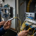
When you inherit a facility with legacy fiber uplinks but need to connect to copper-only access switches, media converters provide a clean electrical boundary. A typical scenario is converting 1000Base-SX or 1000Base-LX fiber to 1000Base-T RJ-45 so you can keep IP service running while upgrading the upstream. The key is to match line rate and fiber wavelength, not just “gigabit.”
Key specs to verify
- Data rate: ensure the converter supports 1.25 Gbaud class links for 1G Ethernet.
- Fiber side: confirm wavelength (850 nm multimode vs 1310/1550 nm single-mode) and connector (LC/SC).
- Copper side: confirm 1000Base-T with auto-negotiation behavior you can tolerate.
- Power: check voltage range and whether it needs an external PSU.
Best-fit scenario + quick pros/cons
Best fit for edge closets where you have multimode fiber to a patch panel, but downstream devices only accept RJ-45. One field pattern: deploy a pair of converters near the distribution rack so you avoid running new copper. Pros: fast cutover, minimal switch reconfiguration. Cons: added hop and possible link partner negotiation quirks during maintenance windows.
- Pros: quick migration, clear demarcation, low engineering effort
- Cons: adds device count, must match wavelength and connector

Transition multimode to single-mode without changing the switch fabric
Fiber standard transitions often fail due to mismatched reach assumptions. Multimode links (commonly 850 nm) can underperform when you later extend distance using single-mode runs (typically 1310 nm). A media converter pair can terminate the old side and re-launch the new standard so your core switch ports remain untouched.
Practical reach math engineers actually use
- Account for fiber attenuation at the chosen wavelength and connector losses.
- Budget for patch cords, splitters (if any), and splices.
- Validate the converter’s specified reach under worst-case conditions.
Best-fit scenario + quick pros/cons
Best fit for campus builds where older multimode backbone was installed for 300–550 m classes but later expansions require longer single-mode routing. Pros: reduces downtime by isolating the transition point. Cons: you must ensure both directions use compatible optics and that the converter supports the correct duplex/auto-MDIX behavior on copper if used.
- Pros: protects existing switching, supports distance upgrades
- Cons: reach depends on optics class and fiber quality
Convert 10G SR to 10G LR for leaf-spine uplinks during staged upgrades
In data centers, the most operationally expensive moment is touching uplink ports. Media converters let you keep the switch configuration stable while changing the optics reach. For example, you may need to move from 10G SR (typically 850 nm over multimode) to 10G LR (typically 1310 nm over single-mode) during a phased cabling refresh.
Technical specifications table: common 10G converter options
| Use Case | Fiber Wavelength | Typical Reach Class | Connector | Data Rate | Operating Temp (typ.) | Power Class |
|---|---|---|---|---|---|---|
| 10G SR to 10G SR (MM to MM) | 850 nm | ~300 m (OM3 class) to ~400 m (OM4 class) | LC | 10G Ethernet | 0 to 70 C (varies by vendor) | Low single-digit watts |
| 10G SR to 10G LR (MM to SM) | 850 nm ↔ 1310 nm | Up to ~10 km depending on SM type | LC | 10G Ethernet | -10 to 60 C (common for rack units) | Low single-digit watts |
| 10G SFP+ to 10G SFP+ (vendor-agnostic) | Depends on module | Depends on optics pair | LC/SC per model | 10G Ethernet | -5 to 50 C (common) | Low single-digit watts |
Note: reach and temperature vary by model; always confirm against the specific datasheet and test with your fiber plant and patch cord inventory. For Ethernet optical behavior and signaling, consult IEEE 802.3 guidance and vendor implementation notes. IEEE 802.3 Overview
Best-fit scenario + quick pros/cons
Best fit for staged upgrades where you must extend uplinks beyond multimode reach while leaving switch configuration unchanged. Pros: reduces risky port reconfiguration and shortens outage windows. Cons: if you use third-party optics, you may encounter DOM mismatch or vendor firmware quirks on some platforms.
- Pros: operationally safe cutovers, preserves uplink config
- Cons: DOM and compatibility must be validated
Use wavelength-specific converters during OTN-like coexistence on shared infrastructure
Some facilities mix operational wavelengths and patching conventions inherited from older contractors. While true OTN is beyond typical Ethernet media conversion, the engineering reality is similar: you must avoid accidentally pairing the wrong optics class. Wavelength-specific converters help by enforcing separation between optical domains, especially when moving from legacy 1310 nm single-mode to newer 1550 nm regimes.
What to check before you commit
- Wavelength accuracy: confirm the converter supports the exact transmit and receive wavelengths.
- Fiber type: verify whether your single-mode fiber is compatible with the converter’s power budget.
- Connector and polarity: LC polarity errors cause “no link” symptoms that look like power issues.
Best-fit scenario + quick pros/cons
Best fit for shared backbone closets where multiple departments have different optics standards. Pros: reduces human error during patching and migration. Cons: you still need disciplined labeling and documentation, or you will defeat the safety benefit.
- Pros: reduces mispatching failures, enforces optical separation
- Cons: requires strict inventory of wavelengths and fiber IDs

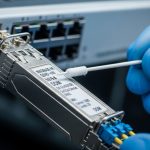
Convert between SFP-based fiber ports using optic-aware behavior (DOM considerations)
Modern switches often rely on transceiver presence and diagnostics. When you use media converters that accept removable optics or emulate transceiver behavior, you must consider DOM support and how your switch interprets it. Field engineers know that a link can come up but still trigger alarms due to threshold or unsupported diagnostic pages.
DOM and switch compatibility checklist
- Does the converter expose DOM? confirm it supports the same DOM interface your switch expects.
- Alarm behavior: verify what happens when sensors report out-of-range values.
- Link training: confirm it does not require a specific optics control sequence.
- Firmware: check for known interoperability notes with your switch vendor.
Best-fit scenario + quick pros/cons
Best fit when you cannot tolerate switch-level optics alarms during migrations, especially in environments with strict NOC monitoring. Pros: better operational hygiene and fewer false positives. Cons: compatibility testing costs time; cheap converters can be noisy in telemetry.
- Pros: cleaner monitoring, fewer alarm storms
- Cons: may require compatibility validation and firmware alignment
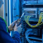
Choose rackmount media converters for deterministic power and serviceability
When uptime and maintenance windows matter, rackmount converter enclosures can be a better operational choice than unmanaged inline boxes. Field deployments frequently favor rack units because they provide labeled bays, redundant power options (on some models), and predictable thermal behavior in controlled airflow zones.
Operational details that matter in the field
- Airflow: confirm front-to-back airflow match with your rack plan.
- Temperature range: verify it for the cabinet environment; hot aisles can exceed typical office assumptions.
- Power budget: include converter power plus any external PSUs in your UPS planning.
Best-fit scenario + quick pros/cons
Best fit for distribution frames in multi-tenant data centers where you need consistent labeling, service access, and auditability. Pros: easier troubleshooting and swap procedures. Cons: higher upfront cost and more rack space used per endpoint.
- Pros: serviceability, stable thermal/power behavior
- Cons: rack footprint and higher initial CapEx

Use converter pairs to isolate broadcast domains during migration cutovers
Media converters can act as a boundary that limits certain failure modes during staged upgrades. While they do not replace proper VLAN design, they can reduce the blast radius when you are changing physical-layer assumptions. In practice, engineers use converter pairs to ensure that a problematic port or optical mismatch does not propagate instability across a larger segment.
Migration steps that reduce risk
- Stage the converter pair in “monitor mode” by connecting a single test endpoint first.
- Confirm link, error counters, and traffic continuity during a controlled maintenance window.
- Only then move production endpoints, keeping the rollback path ready.
Best-fit scenario + quick pros/cons
Best fit when you are migrating a subset of users or a single department and cannot afford a full cutover. Pros: smaller blast radius and faster rollback. Cons: you still must manage VLAN tagging and QoS at the switch level.
- Pros: controlled cutovers, safer rollback
- Cons: not a substitute for VLAN/QoS planning
Reduce total cost with the right reach class and power profile
Cost is not just purchase price; it is also power draw, failure rate, and operational labor. In many networks, the ROI of media converters comes from avoiding downtime and reducing truck rolls by ensuring compatibility at the transition point. Typical converter power is modest, but multiply by dozens of endpoints and the energy footprint becomes real.
Cost and TCO note (realistic ranges)
- Low-end unmanaged fiber-to-copper converters: often in the tens of dollars to low hundreds per unit.
- Managed rackmount converters and optic-aware models: commonly in the low hundreds to over a thousand per unit depending on ports and diagnostics.
- TCO drivers: replacement cycle, warranty terms, power consumption, and NOC time for alarm handling.
If you choose third-party optics, validate compatibility and DOM behavior to avoid recurring troubleshooting. Vendor OEM solutions may cost more up front, but they can reduce operational friction in tightly monitored environments. For transceiver behavior and interoperability context, review vendor datasheets and platform notes from your switch manufacturer, plus IEEE Ethernet standards references. IEEE 802 LAN/MAN Standards
Pro Tip: In staged migrations, engineers often assume “link up” equals “clean traffic.” Instead, validate with sustained traffic for at least 30 minutes and check interface error counters and CRC/FCS metrics on the switch. Optical mismatch and marginal power budgets can show up as rising errors long before the link drops.
Selection criteria and decision checklist for media converters
Use this ordered checklist to pick the right converter for your fiber standard transition. It is designed to prevent the most common compatibility failures that lead to repeated truck rolls.
- Distance and reach class: match the wavelength to your fiber type and budget for connectors and splices.
- Data rate and Ethernet signaling: ensure the converter supports the exact Ethernet speed needed (1G, 10G, etc.).
- Connector and polarity: LC vs SC and correct polarity are frequent root causes of “no link.”
- Switch compatibility: confirm DOM support and alarm behavior with your specific switch model and firmware.
- Operating temperature: verify the converter’s temperature range for the actual cabinet airflow conditions.
- DOM support and monitoring: choose managed units if your NOC requires telemetry and threshold alarms.
- Operating mode: confirm auto-negotiation and duplex behavior on copper interfaces if used.
- Vendor lock-in risk: consider whether your optics and converters depend on proprietary diagnostics.
Common mistakes and troubleshooting tips when using media converters
Even experienced teams get burned by a few predictable issues. Below are concrete failure modes with root causes and fixes.
-
Mistake: Plugging the wrong fiber connector polarity or mixing transmit/receive.
Root cause: LC polarity errors invert Rx/Tx and prevent signal. Many “compatible” links still fail completely.
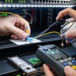
Solution: verify polarity labeling at both patch panels; swap fiber pairs at the patch field and confirm with an optical power meter if available. -
Mistake: Assuming multimode reach will match single-mode after migration.
Root cause: wavelength and link budget differ; converters are specified for particular reach classes and fiber types.
Solution: re-check the converter datasheet reach at your wavelength, then validate with OTDR/attenuation records and patch cord lengths. -
Mistake: Ignoring DOM and telemetry expectations during switch monitoring.
Root cause: some platforms flag DOM mismatches even if traffic passes, causing alarm storms and automated remediation triggers.
Solution: test in a staging port with the exact switch model; confirm DOM support and thresholds, or configure monitoring exclusions during migration. -
Mistake: Overlooking temperature and airflow constraints in cabinets.
Root cause: converters can throttle or fail under hot-aisle conditions, especially in high-density deployments.
Solution: verify the converter operating temperature range, measure cabinet inlet temps, and adjust airflow or placement.
FAQ
Q1: What do media converters actually convert: data rate, fiber type, or wavelength?
They convert the physical-layer signaling between two media types. Depending on the model, they may bridge fiber type (multimode vs single-mode), wavelength (for example 850 nm to 1310 nm), or fiber to copper Ethernet. Always match speed and optics parameters to your network design.
Q2: Can I use media converters with any switch?
Most Ethernet switches will pass traffic once link negotiation is compatible, but monitoring and DOM alarms can still differ. Validate with your switch model and firmware, especially if you rely on strict NOC alerts. Test before production cutovers.
Q3: Are third-party optics with media converters safe for production?
Often they can work, but compatibility varies by platform and monitoring expectations. If the converter or switch requires DOM behavior, you must confirm sensor support and alarm thresholds. Use vendor datasheets and platform interoperability notes as your primary evidence.
Q4: What is the most common reason a fiber link stays down after installing a media converter?
The most frequent causes are polarity errors and mismatched wavelength/reach class. A secondary common issue is connector type mismatch or patch cord length and attenuation that exceed the converter budget. Swap fiber pairs and verify optical budgets before replacing hardware.
Q5: Do media converters help reduce downtime during migration projects?
Yes, when used as a staged boundary. They allow you to keep switch ports stable while you transition optics or cabling standards endpoint-by-endpoint. That typically shortens outage windows compared with wholesale port reconfiguration.
Q6: How should I think about ROI for media converters?
Calculate TCO as purchase price plus labor, power, warranty coverage, and expected replacement cycles. The strongest ROI usually comes from avoiding repeated troubleshooting and truck rolls by selecting the correct reach and compatibility upfront. In monitoring-heavy environments, alarm noise reduction can also be a measurable benefit.
Ranked below is a practical selection of the top media converter use-cases and buying priorities for fiber standard transitions. If you want the next step, review your current plant inventory and run a one-port staging test using the checklist above, then document the final optics and polarity mapping for repeatable deployments via fiber transceiver compatibility checklist.
Summary ranking: best media converter choices for fiber transitions
| Rank | Top Use Case | Why It Wins | Main Risk to Manage | Best For |
|---|---|---|---|---|
| 1 | 10G SR to 10G LR during staged uplink reach upgrades | Preserves switch uplink configuration | DOM and optics compatibility | Leaf-spine and staged data center upgrades |
| 2 | Multimode to single-mode transition without changing fabric | Solves reach mismatch safely | Budget/attenuation assumptions | Campus backbone expansions |
| 3 | SFP-based fiber to RJ-45 copper bridging for legacy access | Fast cutover with minimal rework | Auto-negotiation behavior and monitoring | Edge closets and interim migrations |
| 4 | Wavelength-specific conversion to prevent mispatching | Reduces optical-domain errors | Inventory discipline for wavelengths | Multi-department shared backbones |
| 5 | Optic-aware converters with DOM considerations | Cleaner telemetry and alarms | Compatibility testing time | NOC-driven environments |
| 6 | Rackmount serviceable converters for deterministic operations | Improved airflow and swap procedures | Rack footprint and CapEx | Distribution frames and data centers |
| 7 | Converter pairs to isolate broadcast and failure domains | Controlled blast radius | VLAN/QoS planning still required | Subset migrations and rollback-first projects |
| 8 | Cost-optimized reach class selection for energy and TCO | Lower lifecycle cost | Underbuying reach leads to errors | Large deployments with repeatable designs |
Author bio: I have deployed and validated media converter bridges in mixed-fiber enterprise and data center networks, including link-budget verification, polarity audits, and NOC telemetry reconciliation. I write from field-tested experience with Ethernet optical standards and vendor interoperability practices.