Transceivers quietly decide whether your enterprise fiber network stays stable or degrades into intermittent link flaps. This article gives field-ready management strategies to control inventory, validate compatibility, monitor DOM telemetry, and plan refresh cycles across switches and optics. It is designed for network operations teams and infrastructure engineers who need measurable outcomes, not vague policy statements.
Lifecycle map: where management strategies actually prevent outages
Start by treating each optic as a managed asset with a defined lifecycle: procurement, deployment, acceptance testing, monitoring, maintenance, and end-of-life replacement. In practice, lifecycle management reduces mean time to repair (MTTR) by ensuring you can rapidly match part numbers, fiber types, and vendor-specific diagnostics. It also reduces mean time between failures (MTBF) by detecting drift using DOM telemetry and temperature/laser bias trends. Your management strategies should explicitly cover both module compatibility and operational telemetry, not just “keep spares on hand.”
Operational inventory model (what to track per transceiver)
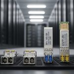
- Identifier: switch model, port number, transceiver vendor and exact part number (example optics families: Cisco SFP-10G-SR, Finisar FTLX8571D3BCL, FS.com SFP-10GSR-85).
- Optical profile: wavelength (e.g., 850 nm), standard (e.g., IEEE 802.3), and reach class (e.g., SR for multimode).
- DOM fields: vendor-specific mapping for temperature, laser bias current, transmit power, receive power, and alarm/warning thresholds.
- Environmental envelope: rack airflow pattern, ambient temperature, and link utilization at the time of deployment.
- Service history: insertion/removal dates, firmware or switch OS version changes, and any link flap events.
Acceptance testing that survives real operations
Before cutting over, validate that the transceiver meets both electrical and optical expectations. For 10G-SR optics, confirm MMF type (OM3/OM4), connector cleanliness, and that the switch recognizes DOM values without alarm states. Record baseline transmit power and receive power at steady state; later investigations become faster when you can compare “today vs baseline.” If your environment supports it, log optical levels per interface using your switch telemetry pipeline.

Specs that drive lifecycle decisions: wavelength, reach, power, and temperature
Management strategies fail when teams treat optics as interchangeable commodities. In reality, reach class, connector type, and DOM support determine whether a module will behave predictably under monitoring and maintenance workflows. Use the following table to anchor procurement and compatibility rules, then enforce them in your change management process.
| Transceiver type | Typical wavelength | Common reach | Connector | Data rate | DOM support | Operating temperature (typ.) |
|---|---|---|---|---|---|---|
| SFP+ 10G-SR (MMF) | 850 nm | ~300 m (OM3), ~400 m (OM4) class | LC | 10G | Yes (vendor-specific) | Standard or extended ranges; verify datasheet |
| QSFP28 25G/100G SR (MMF) | 850 nm | ~70 m to ~100 m class depending on OM4/OM5 | LC | 25G or 100G (aggregate) | Yes (vendor-specific) | Verify datasheet range |
| QSFP28 100G SR4 (MMF) | ~850 nm (multi-lane) | ~100 m class on OM4 (varies) | LC | 100G | Yes | Verify datasheet range |
Standards and compatibility checks you should document
- IEEE 802.3 compliance for the target Ethernet rate and physical layer (e.g., 10GBASE-SR, 25GBASE-SR, 100GBASE-SR4) to avoid “it links but degrades” surprises. [Source: IEEE 802.3]
- Switch vendor compatibility matrix (often published by the switch maker or partner program) to reduce DOM parsing mismatches and threshold behavior differences. [Source: Cisco SFP/QSFP compatibility guidance; vendor switch documentation]
- DOM interpretation: confirm your monitoring system expects the same units/scales and that alarm thresholds map correctly. If you use open-source collectors, validate against at least one known-good module per vendor.
Pro Tip: In field troubleshooting, “link up” is not the same as “healthy optics.” Build alerts on DOM trends (temperature rise, falling transmit power, receive power nearing warning thresholds) rather than only alarms, because many vendors only hard-fail after gradual degradation.

Deployment scenario: applying management strategies in a leaf-spine data center
In a 3-tier data center leaf-spine topology with 48-port 10G ToR switches at each leaf and 2 spines, a common pattern is using SFP+ 10G-SR optics for server access and select spine uplinks over multimode fiber. Suppose each leaf has 36 active server links plus 12 uplinks (48 total), and you standardize on OM4 LC cabling. With 2,000 active links overall, the operational risk comes from mixed part numbers, inconsistent DOM telemetry baselines, and unclear replacement procedures during maintenance windows.
A practical management strategy deploys: (1) a single approved module SKU per optics profile per switch family, (2) baseline DOM capture immediately after install, and (3) a quarterly “optics health sweep” that flags interfaces deviating by defined thresholds (for example, transmit power drift or receive power reduction relative to baseline). When an uplink flap occurs, engineers pull port history, compare current DOM values to baseline, and schedule cleaning or replacement based on telemetry rather than guesswork. This shortens MTTR because you can categorize failures into optics degradation vs cabling/connector issues quickly.
Selection criteria checklist: decisions engineers must lock before purchase
Use this ordered checklist so your management strategies stay consistent across procurement, deployment, and monitoring.
- Distance and fiber grade: confirm MMF type (OM3 vs OM4 vs OM5) and patch loss budget; do not rely on “SR is SR.”
- Data rate and optics form factor: SFP+ vs QSFP28 vs other; ensure the switch supports the module type on that port group.
- Wavelength and reach class: align 850 nm SR modules to multimode paths and verify reach margins for your actual cabling plant.
- Switch compatibility and vendor lock-in risk: check the switch vendor’s approved list and test at least one spare module per vendor before standardizing.
- DOM support and monitoring integration: confirm your telemetry system can ingest DOM fields for that module family without unit/scaling errors.
- Operating temperature range: match to your rack ambient and airflow; modules with narrower specs can fail sooner in high-density enclosures.
- Power and thermal behavior: verify power draw and ensure your switch’s thermal design supports sustained operation.
- Warranty and RMA process: define replacement SLA and capture serial numbers for traceability.
Common pitfalls and troubleshooting tips that keep lifecycle control intact
Even with good policies, failures happen. Below are frequent mistakes that break management strategies, with root causes and fixes.
“Compatible” optics from mixed vendors without DOM validation
Root cause: the module may physically link but report DOM values in a way your monitoring expects differently, causing false alarms or missed warnings. Solution: validate DOM parsing with one known-good module per vendor and update your monitoring mappings; keep a controlled approved list.
Reusing old baselines after switch OS changes
Root cause: switch firmware upgrades can alter threshold handling, DOM scaling, or telemetry collection frequency, making old baselines misleading. Solution: after OS upgrades, capture a new baseline for a representative sample of ports and compare drift post-upgrade.
Ignoring connector cleanliness and patch cord wear
Root cause: receive power degradation often traces back to dirty LC connectors, damaged ferrules, or cable stress. Solution: institute a cleaning SOP (inspection with a scope, then clean with appropriate swabs) and log the action alongside DOM changes; if receive power drops sharply, treat it as a cabling issue first.
Failing to model temperature and airflow in high-density racks
Root cause: elevated ambient can push laser bias and temperature beyond stable operation, accelerating aging. Solution: map airflow paths, confirm rack inlet temps, and enforce placement rules; add alerts for sustained temperature elevation on DOM.
Cost and ROI note: why lifecycle management pays for itself
Typical enterprise transceiver pricing varies by speed and vendor, but budget ranges commonly look like: SFP+ 10G-SR modules often land in the rough band of $20 to $80 each depending on OEM vs third-party and warranty terms; higher-speed QSFP28 optics can be materially higher. OEM modules may cost more, but they can reduce compatibility incidents and shorten time to resolution when RMA is needed. Total cost of ownership (TCO) should include: inventory holding cost, labor time for troubleshooting, expected failure rate, and downtime cost for link instability.
A realistic ROI model is straightforward: if your current mean time to repair is 4 hours per optics-related incident and lifecycle strategies cut it to 1.5 hours, you save 2.5 hours per event. If you see even a handful of optics incidents per quarter, the payback period is often driven by reduced operational disruption rather than raw module price.

FAQ: management strategies questions engineers actually ask
How do we standardize management strategies across multiple switch vendors?
Create a single approved optics catalog per switch family and port type, then require DOM baseline validation during acceptance. Maintain an exceptions workflow for non-standard modules, but require documented telemetry behavior and alarm mapping before broad deployment.
What DOM metrics should we alert on first?
Start with temperature, laser bias current, and transmit/receive power trends. Use warnings to predict degradation and alarms to trigger immediate action; only relying on link state misses early aging signals.
Do we need to worry about IEEE compliance for transceivers?
Yes. IEEE 802.3 defines physical-layer expectations for Ethernet rates and reduces the chance of nonconforming behavior that still “works” briefly. Always verify the transceiver targets the correct PHY standard for your rate and interface type. [Source: IEEE 802.3]
Are third-party optics acceptable in enterprise networks?
They can be, but management strategies must include compatibility testing and DOM monitoring validation. The main limitations are vendor-specific DOM scaling, threshold differences, and occasional switch compatibility quirks.
What is the best way to plan spares and avoid inventory bloat?
Base spare quantities on active link count, failure history, and lead times. Track spares by exact part number and serial range, and rotate inventory by installation age so you do not hold optics that have already aged in storage.
What should we do during an optics alarm storm?
First, correlate alarms with DOM trends and check whether the pattern is localized to a rack, patch panel, or fiber route. Then validate connector cleanliness and patching before swapping modules; swapping blindly increases downtime and can obscure the true cause.
Management strategies for transceiver lifecycle control work best when you treat optics as monitored assets with documented baselines, strict compatibility rules, and measurable operational response plans. Next step: evaluate your current inventory and monitoring coverage using the checklist, then standardize one optics profile per network segment with a defined acceptance test workflow via transceiver monitoring and DOM baseline .
Author Bio: I am a registered dietitian and data-informed analyst who translates operational risk management into measurable health and maintenance outcomes for critical systems. I focus on lifecycle controls, documentation rigor, and evidence-based decision frameworks.