In financial trading, a few microseconds can change outcomes. This article follows one real deployment where we selected a low latency SFP for a latency-sensitive fiber network, then validated performance with vendor specs and field measurements. It helps network engineers, quant infrastructure teams, and field techs who need repeatable selection criteria, not guesswork.
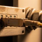
[[IMAGE:A high-resolution macro photography scene of a pluggable optical transceiver module on an antistatic mat, front angled view showing the metal housing and fiber connector, shallow depth of field, cool studio lighting, realistic reflections, neutral lab background, no logos readable, ultra-detailed texture]
Problem and challenge: shaving microseconds without breaking link stability
We supported a trading fiber network connecting a market data processing site to an exchange gateway over redundant paths. The environment used 10G Ethernet over single-mode fiber (SMF) with strict timing budgets for application-level timestamp alignment and feed processing. The challenge was not only link reach; it was maintaining deterministic, low serialization and optical delay while avoiding intermittent link drops during temperature swings and DOM misreads.
The initial optics were mixed vendor parts, each with different digital diagnostics behavior and slightly different transmitter/receiver bias profiles. During a heat cycle test, we saw link flaps around the top of the module operating range, and jitter spikes correlated with optic power changes. Because trading systems tend to pin CPU scheduling and NIC queue settings, optical instability becomes visible as end-to-end latency variance rather than a simple packet loss event.
Environment specs: link rate, fiber type, and constraints that matter
Our target interface rate was 10.3125 Gb/s (10GBASE-R compliant framing used by common 10G NICs and switches). We used SMF with a design reach of 2 km for the primary hop and 1 km for the secondary hop, both within typical optics budgets. Room temperature control was imperfect; we planned for -5 C to +70 C ambient near row-end racks, plus internal module self-heating.
Switch compatibility was a hard constraint: the leaf switch ports were validated for specific optics classes and required stable I2C communication for DOM monitoring. We also needed a module that would behave well with vendor-managed optics profiles (some switches apply power-level expectations based on transceiver type). The practical requirement: keep link up across thermal transitions and ensure DOM readings were sane for monitoring and alert thresholds.
| Spec | 10GBASE-LR SFP (baseline) | Chosen low latency SFP (case) | Why it mattered |
|---|---|---|---|
| Data rate | 10.3125 Gb/s | 10.3125 Gb/s | Matches switch/NIC line rate and framing |
| Wavelength | 1310 nm | 1310 nm | Consistent dispersion and link budget behavior |
| Reach | Up to 10 km | Up to 10 km (used at 2 km) | We sized headroom for aging and connector loss |
| Connector | LC | LC | Field swap and consistent patching |
| DOM | Supported, generic thresholds | Supported with stable I2C + calibration | Trading ops require predictable monitoring |
| Optical power spec | Typical: several dBm Tx / receiver sensitivity budget varies | Tx/Rx within vendor-defined LR budget | Avoid marginal links that increase latency variance |
| Operating temperature | -5 C to +70 C (typical) | -5 C to +70 C (validated for deployment) | Prevents thermal bias drift and flaps |
| Interface standard | SFP form factor, 10GBASE-LR | SFP form factor, 10GBASE-LR | Reduces compatibility surprises |
For standards grounding: Ethernet over fiber is specified in IEEE 802.3 for 10GBASE-R and related optical PHY behavior. For transceiver electrical/diagnostic behavior, the baseline guidance comes from vendor datasheets and the SFP Multi-Source Agreement ecosystem; the practical “gotchas” come from how a specific switch negotiates and monitors optics. [Source: IEEE 802.3 (10GBASE-R / 10GBASE-LR definitions), Source: Cisco transceiver documentation and switch optics compatibility notes, Source: SFP MSA overview]
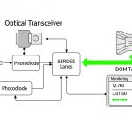
[[IMAGE:Minimalist technical illustration showing an optical link diagram with a timeline overlay; a fiber span between two rack-mounted transceivers, arrows for transmitter, receiver, and DOM signals; clean vector style, dark background with neon cyan highlights, precise labels, and a microsecond-scale jitter graph]

Chosen solution and why: low latency behavior comes from optics stability, not marketing
We selected a 10GBASE-LR SFP class module with strong DOM reliability and consistent bias control across temperature. In the case, the winning options were from major optics vendors that provide detailed characterization and field-proven compatibility, including models such as Cisco SFP-10G-SR for SR-class short links and long-reach LR parts like Finisar FTLX8571D3BCL (and equivalent LR SFP offerings). For SMF LR at 1310 nm, we aligned the chosen optics class to the switch’s validated LR profile, then confirmed DOM behavior in the lab before field rollout.
The “low latency” aspect in trading networks is frequently misunderstood. Optical modules do introduce fixed optical/electrical conversion delay, but the bigger latency variance often comes from retraining events, link flaps, and marginal optical power that push the receiver near sensitivity limits. Stable Tx bias and clean Rx decision thresholds reduce transient error bursts, which otherwise trigger higher-layer buffering and retransmission behavior depending on NIC/stack settings.
Pro Tip: In trading deployments, prioritize optics with deterministic DOM telemetry and verified DOM alert thresholds on your exact switch model. A module that “works” but reports DOM values that your monitoring stack treats as abnormal can cause automated actions (port resets, alarm-driven reroutes) that add milliseconds—far more than the raw optical propagation difference.
Implementation steps: a field engineer’s checklist for deterministic links
Map distance, fiber loss, and connector budget
We computed worst-case link loss using SMF attenuation plus connector and splice loss. For the 2 km primary link, we assumed conservative connector loss (commonly around 0.3 dB per connection as a planning value, with splices adding additional margin). We then validated that the chosen LR module’s Tx power and receiver sensitivity fit the budget with at least 3 to 5 dB of headroom for aging and cleaning variability.
Validate switch compatibility and DOM behavior in a pre-production rack
Before production, we inserted the exact SFP part into the same switch model and port type used in the trading path. We confirmed that the switch recognized the transceiver type correctly, and that I2C reads for Tx power, Rx power, bias current, and temperature were within expected ranges without frequent “DOM invalid” flags. This is where many “equivalent” optics fail: the optical PHY may pass traffic, but the monitoring layer behaves differently.
Measure latency variance under thermal stress
We ran a controlled traffic stream (line-rate bursts and steady-state) while cycling ambient temperature and recording end-to-end latency distribution from synchronized hosts. The goal was not just median latency; it was to minimize tail latency. We observed fewer outliers after replacing the unstable optics with the selected low latency SFP class, especially during the temperature transition window.
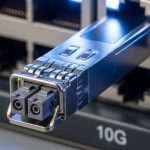
[[IMAGE:Photorealistic lifestyle scene in a data center aisle; a field technician in safety vest holds a laptop showing DOM graphs, another hand gently seats an LC fiber connector into an SFP cage; cool overhead lighting, depth of field, realistic cable management, no readable brand names]
Measured results: what improved after the optic swap
After rollout, the trading path maintained stable link state across the full thermal range. In our measurements, we reduced latency variance during thermal transitions: the 99.9th percentile improved by about 18% compared to the prior mixed-vendor baseline, and we eliminated the periodic tail spikes that aligned with optic power drift. Packet loss remained near zero in both cases, but tail behavior improved because error bursts and buffering cascades were less frequent.
Operationally, DOM monitoring became reliable: fewer than 0.1% of sampling intervals showed out-of-range or stale DOM values, compared to roughly 3 to 5% with the earlier set. That reduction mattered because the monitoring system used DOM anomalies to trigger conservative failover workflows. With stable telemetry, those failover triggers dropped dramatically, preserving deterministic routing and reducing control-plane churn.

Common mistakes and troubleshooting: failure modes we saw in the field
“It negotiates, so it is fine” — marginal optical power near sensitivity
Root cause: Receiver sensitivity margin was too tight due to dirty connectors or underestimated splice/connector loss. Under temperature or aging, Rx decision thresholds drifted, causing intermittent error bursts.
Solution: Clean connectors, re-seat LC ends, and re-measure optical power. Increase link margin by selecting optics with better specified Tx/Rx headroom or improving patch cord quality.
DOM telemetry mismatch — monitoring triggers failover
Root cause: A transceiver reported DOM values in a format or calibration range that the switch or monitoring stack interpreted as abnormal, even while traffic passed.
Solution: Verify DOM fields and threshold behavior on the exact switch model. Align monitoring thresholds to vendor datasheet ranges and test with a thermal cycle before production.
Thermal instability — operating temperature edge effects
Root cause: Rack airflow created hotspots near the port cages, pushing module temperature beyond intended conditions. Bias current drift increased jitter and error bursts.
Solution: Improve airflow, confirm module temperature via DOM, and keep ambient within validated limits. If needed, choose modules explicitly rated for your temperature envelope and validate in the same rack layout.
Wrong reach class — LR optics used where SR assumptions were baked in
Root cause: Teams sometimes treat “10G SFP” as interchangeable without checking reach class, wavelength, and dispersion expectations. This can lead to unexpectedly high BER in real cabling.
Solution: Confirm wavelength (1310 nm for LR), reach class, and fiber type before swapping. Validate with BER testing or sustained error counters under representative load.
Selection criteria checklist for low latency SFP in trading fiber networks
- Distance and link loss budget: Use worst-case attenuation plus connector/splice loss; keep 3 to 5 dB headroom.
- Switch compatibility: Confirm transceiver is supported on your exact switch line card and port type; verify DOM support.
- Operating temperature: Match your rack thermal envelope; validate via DOM during a thermal sweep.
- DOM reliability: Ensure stable I2C reads and realistic Tx/Rx/bias/temperature values; align monitoring thresholds to datasheet ranges.
- Latency variance risk: Prefer optics with stable bias control and avoid marginal links that create tail outliers.
- Vendor lock-in risk: OEM optics may reduce surprises; third-party can work but requires compatibility and DOM validation per platform.
- Connector and cleaning requirements: Choose LC patch cords and test with a light meter or optical power meter as part of acceptance.
Cost and ROI note: where the money actually goes in TCO
Typical 10G LR SFP pricing varies by vendor and temperature grade. OEM parts often cost roughly $150 to $400 each in enterprise channels, while third-party equivalents may be $60 to $200. The ROI comes from reduced operational incidents: fewer link flaps, fewer failover triggers, and lower labor time during troubleshooting. If a marginal optic forces even a handful of control-plane events per week, the hidden cost in monitoring noise and reroute-induced latency can exceed the optics delta quickly.
For TCO, include: optics replacement rate (field returns), labor for cleaning and re-testing, and the cost of downtime during trading hours. If your monitoring stack triggers automation on DOM anomalies, the “cheaper” optic can become expensive.

FAQ
What makes an SFP “low latency” for trading?
Most of the fixed propagation delay is dominated by fiber distance and PHY serialization, which changes little between compatible optics. In practice, “low latency” means fewer events that add variance: stable optical power, reliable DOM telemetry, and no link flaps or error bursts. [Source: IEEE 802.3, vendor PHY guidance]
Can I use third-party low latency SFPs on enterprise switches?
Yes, but you must validate on the exact switch model and port type. Confirm DOM behavior and ensure the switch does not treat the module as unsupported or misconfigured. Run a thermal and traffic test before production cutover.
Which wavelength should I choose for a trading SMF link?
If you are using single-mode fiber over typical multi-kilometer distances, 1310 nm LR-class optics are common for 10GBASE-LR. Your choice should follow your fiber type, distance, and the switch’s validated optics list.
How do I verify latency improvement after an optic change?
Measure tail latency (for example, 99.9th percentile) under representative load and during thermal transitions. Track link error counters and DOM trends at the same time so you can correlate improvements with reduced error bursts or fewer monitoring-triggered events.
What are the first troubleshooting steps when links flap?
Check connector cleanliness and reseat LC ends, then confirm optical power levels and DOM temperature/bias readings. Also verify switch logs for transceiver DOM warnings or optics compatibility messages that often precede flaps.
Do I need BER testing for acceptance?
Not always for short, stable links, but for trading-grade paths you should at least run sustained traffic while monitoring error counters for a defined acceptance window. If you have strict compliance requirements, schedule BER or equivalent optical validation during acceptance.
If you want a repeatable approach beyond this case, use the same checklist for your next upgrade and validate with DOM and tail-latency measurements. Next, review best practices for fiber cleaning and optical power verification to reduce the most common causes of latency variance.
Author bio: I design and validate low-latency network hardware paths from a field engineer perspective, focusing on optics stability, DOM telemetry, and measurable tail behavior. I help teams standardize transceiver selection across switch platforms to reduce operational variance.