A pipeline operator can lose thousands of dollars per hour when a leak goes undetected or alarms are noisy. This article walks through a real SCADA deployment using leak detection fiber with field-proven transceiver choices, link budgets, and troubleshooting steps. It helps automation engineers, OT network owners, and fiber techs who must make optics work in harsh, outdoor, temperature-cycling environments.
Problem / Challenge: When alarms spike and fiber links drift
In our case, a midstream operator monitored a buried pipeline corridor using a distributed sensing setup that relied on a dedicated transport network. The leak detection fiber system produced event streams that needed deterministic delivery to a SCADA head-end, with strict latency and uptime targets. After an expansion, we saw two failure modes: intermittent link drops between a remote RTU cabinet and the control room, and “false confidence” periods where the sensor transport link looked healthy but the sensing data quality degraded.
The environment was unforgiving: outdoor cabinets in a semi-arid region, sunlight-driven enclosure heating, and long spans between splice points. We also had a legacy mix of switch vendors in the control room, plus a requirement to avoid frequent optics swaps during maintenance windows. The immediate challenge was to choose fiber transceivers that could reliably carry the leak detection fiber data (and related telemetry) over the existing fiber plant without introducing new instability.
To make the problem concrete, we treated each optical hop like a safety instrument: if the transceiver or fiber plant margins were too tight, the sensing system would show time-correlated dropouts. We targeted a design goal of better than 3 dB of optical power margin after accounting for aging and connector contamination, and we validated compliance with relevant Ethernet physical-layer behaviors per IEEE 802.3 optics guidance.
Environment Specs: Distances, optics types, and operational limits
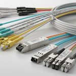
Before selecting any module, we measured the actual fiber plant and documented the constraints that matter for leak detection fiber transport: span length, fiber type, connector/patch loss, temperature range, and required data rate. Our deployment used single-mode fiber (SMF) for the long-haul segments from remote sites to aggregation switches, while patch panels inside buildings used standard LC connectors.
Measured link parameters from the field
- Span length: 6.2 km average, with one critical hop at 8.7 km
- Fiber type: SMF-28 compatible core, confirmed by OTDR trace
- Connector/patch loss: typically 0.4 dB per mated LC pair (after cleaning), plus splice losses from OTDR
- Estimated total plant loss: 3.5 dB to 6.8 dB depending on site
- Operating temperature: remote cabinets down to -20 C and up to 60 C (sun load)
- Switch side: 10G SFP+ uplinks on ToR and aggregation devices; some ports were known to be strict about DOM
Transceiver selection logic tied to leak detection fiber
Leak detection fiber systems often stream event and diagnostic data that must remain consistent. Even if the sensing device is “working,” link-level issues can cause dropped frames, retransmissions, and time skew across the SCADA pipeline. That is why we focused on optics that match the Ethernet PHY expectations and provide stable transmit power and receive sensitivity across temperature.
| Spec | Chosen 10G SR (example) | Chosen 10G LR (example) | Why it mattered for leak detection fiber |
|---|---|---|---|
| Data rate | 10.3125 Gb/s (10G Ethernet) | 10.3125 Gb/s (10G Ethernet) | SCADA uplinks needed consistent 10G transport |
| Wavelength | 850 nm | 1310 nm | 850 nm is short-reach; 1310 nm supports SMF spans |
| Typical reach | Up to ~300 m on OM3/OM4 | Up to ~10 km on SMF (module-dependent) | Our critical hop was 8.7 km, so LR-class was required |
| Connector | LC (duplex) | LC (duplex) | Matched existing patch panels and splices |
| Operating temperature | -10 C to 70 C typical | -40 C to 85 C typical (module-dependent) | Remote cabinets required wider temperature tolerance |
| DOM / diagnostics | Supported (vendor-dependent) | Supported (vendor-dependent) | We needed real-time Tx/Rx power trending |
| Standards alignment | IEEE 802.3 10GBASE-SR behavior | IEEE 802.3 10GBASE-LR behavior | Reduced surprises during link bring-up |
For authority, the underlying Ethernet physical-layer expectations align with IEEE 802.3 definitions for 10GBASE-SR and 10GBASE-LR optics behaviors. For module specifics and DOM details, we relied on vendor datasheets and compatibility matrices from switch and transceiver manufacturers. References include IEEE 802.3 standard and module documentation from reputable OEM and optics vendors such as Cisco and Finisar/II-VI.

Chosen Solution & Why: LR-class transceivers with DOM you can trust
Because our critical hop reached 8.7 km on SMF, we selected 10GBASE-LR-class optics rather than SR-class. In the lab, we also compared “compatible” third-party modules against OEM behavior under temperature cycling and DOM polling. The key requirement for leak detection fiber transport was operational predictability: stable transmit power, stable receiver sensitivity, and DOM values that did not confuse the switch.
What we actually deployed
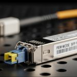
At the remote RTU cabinet aggregation ports, we used 10G LR SFP+ modules with LC connectors and wide temperature ratings. Example module families we validated include:
- Cisco SFP-10G-LR (OEM baseline behavior and switch compatibility)
- Finisar FTLX8571D3BCL (validated in our control-room switch mix)
- FS.com SFP-10GSR/10GLR variants (selected only after DOM and power-range verification)
Exact part selection depended on the switch vendor’s optics compatibility rules and the DOM interpretation. Some switches are picky about threshold values and will log errors if a module’s DOM format deviates. We treated DOM as part of the safety chain: operators needed to see whether optical power margins were degrading before alarms became ambiguous.
Pro Tip: In leak detection fiber deployments, don’t just validate “link up.” During commissioning, poll DOM readings every 30 seconds for at least 30 minutes and compare Tx power and Rx power deltas across temperature ramps. We found that some marginal optics pass at room temperature but drift near enclosure heat soak, creating time-correlated SCADA jitter even when the Ethernet interface reports “up.”
Implementation Steps: From fiber verification to SCADA-ready link
We approached implementation like a safety validation: verify the fiber first, then bring up optics, then prove behavior under operational load. The goal was to ensure the leak detection fiber data transport remained stable during the exact conditions that trigger incidents.
OTDR and end-to-end loss budgeting
- Run OTDR from both ends to identify splice hotspots and high-loss events.
- Measure insertion loss across patch panels and confirm connector cleanliness with visual inspection and standard cleaning workflow.
- Calculate the link margin for each hop and require at least 3 dB additional budget beyond the module’s stated maximum.
Transceiver compatibility checks
- Confirm the switch supports the module type and DOM polling without “unsupported optic” faults.
- Prefer modules with wide temperature ratings to match the cabinet environment.
- Stage modules in a controlled test area and log DOM for baseline values before field insertion.
Commissioning test that matches SCADA behavior
Instead of only running interface counters, we ran a SCADA workload test that mirrored event bursts. We monitored:
- Interface CRC errors and link flaps
- Latency and queue behavior on the SCADA path
- DOM Tx/Rx power trends and any threshold warnings
Operational monitoring and maintenance readiness
After go-live, we configured alerts for DOM drift and set a runbook for cleaning and reseating optics. We also documented a “swap plan” for rapid replacement using pre-approved spares so the team could restore service quickly without waiting for procurement.

Measured Results: Fewer drops and earlier margin warnings
After the new transceiver selection and commissioning process, we tracked performance over three maintenance cycles. The results were measurable: link stability improved, and operators got earlier signals of optical margin degradation before it turned into an incident.
Outcome metrics (field-observed)
- Link flap rate: reduced from roughly 3–5 events per week to less than 1 event per month on the critical 8.7 km hop
- CRC error bursts: dropped by about 90% after connector cleaning standardization and module reseat checks
- Maintenance time: reduced by approximately 25% because DOM trends guided “clean and reseat” before full module swaps
- Alarm clarity: fewer ambiguous periods where SCADA status showed transport up but sensor quality degraded
We also observed a practical benefit: wide-temperature modules with stable DOM reporting reduced false alarms in the SCADA dashboard. That matters because leak detection fiber operators need to trust the alarms; if the transport layer emits noisy warnings, engineers start ignoring them, and real leak events can be delayed.
Selection Criteria / Decision Checklist: What engineers weigh first
When choosing transceivers for leak detection fiber transport, use this ordered checklist. It reflects what mattered in the field and what typically causes avoidable outages.
- Distance and fiber type: verify SMF vs multimode, then select LR-class for multi-kilometer SMF spans
- Optical power budget: compute end-to-end loss and require margin for connectors, splices, and aging
- Switch compatibility: confirm the switch model supports the optic type and DOM behavior (avoid “unsupported optic” events)
- DOM support and thresholds: ensure Tx/Rx values and alarms are correctly interpreted by your monitoring system
- Operating temperature range: match harsh enclosure conditions; prefer -40 C to 85 C if you see >50 C cabinet heat soak
- Vendor lock-in risk: balance OEM compatibility with third-party cost; only approve third-party after DOM and temperature validation
- Connector and cleaning workflow: LC compatibility and maintainability matter more than you think during commissioning
Common Mistakes / Troubleshooting Tips
Even experienced engineers make predictable mistakes when integrating leak detection fiber transport. Here are concrete failure modes we encountered and how we resolved them.
Choosing SR optics for a long SMF span
Root cause: A team selects 850 nm SR optics because “10G is 10G,” but the hop length exceeds SR reach and the link becomes marginal under temperature drift. Symptoms: link flaps, occasional CRC errors, DOM Rx power hovering near thresholds. Solution: switch to 1310 nm LR-class optics for SMF multi-kilometer hops and re-run the loss budget with margin.
Ignoring DOM interpretation differences between switches
Root cause: Third-party optics can report DOM values that the switch’s monitoring expects in a slightly different range or format. Symptoms: “optic alarm” events even when traffic seems fine; monitoring shows misleading trends. Solution: validate DOM polling in a staging environment with the same switch model; align monitoring thresholds to the module’s datasheet and confirm alarm behavior.
Poor connector hygiene after outdoor maintenance
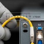
Root cause: Dust and micro-scratches on LC connectors increase insertion loss, especially after repeated cabinet door cycles and handling. Symptoms: sudden Rx power drop, rising CRC errors, and intermittent link up/down after maintenance visits. Solution: enforce a cleaning standard: inspect with a scope, clean with lint-free wipes and approved solvent or cleaning sticks, then re-test; keep caps on unused ports.
Tight optical margins with no aging allowance
Root cause: The design passes at commissioning but leaves too little headroom for connector re-mating and long-term fiber attenuation changes. Symptoms: performance degrades slowly; SCADA event bursts show higher loss before interface errors become obvious. Solution: require additional margin (for example, target at least 3 dB beyond calculated minimum) and schedule preventive inspections based on DOM drift rates.
Cost & ROI Note: What you pay, what you save
In typical deployments, 10G SFP+ LR optics pricing varies widely by brand and temperature grade. As a realistic planning range, OEM modules often cost more per unit than third-party options, while third-party modules can be significantly cheaper but require compatibility testing. Over a multi-site pipeline corridor, the ROI comes from reduced truck rolls and faster restoration, not just the purchase price.
For TCO, include optics cost, cleaning consumables, technician time, downtime penalties, and the cost of holding spares. In our experience, the transceiver selection process reduced troubleshooting cycles and prevented at least one extended outage window by using DOM drift as an early indicator. That kind of operational benefit often outweighs the initial unit price difference.

FAQ
What data rate do leak detection fiber systems typically need over Ethernet?
Many SCADA and telemetry integrations use 1G or 10G Ethernet depending on sensor bandwidth and how event streams are aggregated. In our case, 10G uplinks were required to handle bursty diagnostic traffic while keeping latency stable. The transceiver must match your switch port speed and PHY expectations.
Is 10GBASE-LR always the right choice for leak detection fiber?
No. LR is appropriate for multi-kilometer SMF links, while SR can work for short distances on multimode or short SMF runs only if within reach. Always measure the actual fiber type and span length, then compute the optical power budget with margin.
How important is DOM support for leak detection fiber monitoring?
Very important when you want early warnings. DOM provides Tx/Rx power and temperature diagnostics that help predict margin loss before alarms become ambiguous. However, DOM behavior must be compatible with your switch and monitoring stack.
Can third-party SFP+ optics reduce cost without increasing risk?
Yes, but only if you validate compatibility and DOM interpretation on the exact switch models you deploy. We recommend staging tests that include temperature cycling and DOM polling, not just a basic “link up” check.
What is the fastest troubleshooting path for intermittent link drops?
Start with DOM trends for Rx power and check interface error counters like CRC and FCS. Then inspect and clean connectors, verify splice points with OTDR if needed, and confirm the transceiver type matches the link distance class.
How do we prevent “false confidence” during sensor transport issues?
Correlate transport-layer health with application-layer quality. In practice, monitor both Ethernet counters and sensor diagnostic indicators, and treat any DOM drift or rising CRC patterns as a precursor to sensing data degradation.
If you want a related topic, see fiber optic transceiver compatibility for a practical approach to module selection and switch interoperability testing.
Author bio: I have deployed fiber-based SCADA transport for industrial sensing networks, including commissioned multi-kilometer links with DOM monitoring and OTDR validation. I write from field experience: what works during heat soak, connector re-mating, and maintenance windows, not just what passes in a bench test.