In leaf-spine and campus core designs, a single mis-matched fiber transceiver can destabilize a Link Aggregation Group (LAG) and trigger hash flaps, CRC bursts, or member churn. This guide helps network engineers and field technicians choose and validate LACP SFP optics for consistent forwarding behavior across switch pairs. You will get a deployment checklist, spec comparisons, and failure-mode troubleshooting grounded in IEEE 802.3 and vendor operational constraints. Update date: 2026-04-30.
LACP behavior with fiber links: what must match
LACP aggregates member links at Layer 2 using an actor/partner negotiation state machine and then hashes flows to member ports. In practice, member links must present consistent physical-layer characteristics and operational parameters, otherwise you can see uneven error rates and link-state transitions that cause LAG re-convergence. IEEE 802.1AX specifies the control-plane aspects of LACP, while IEEE 802.3 defines optical electrical behavior for each transceiver class. For LACP SFP, the most operationally relevant constraints are: identical speed/duplex mode (for SFP copper this is different, but for fiber it is typically fixed), consistent optics class (SR vs LR vs ER), stable receive power, and predictable link error counters.
Engineer-facing matching rules
When you build a LAG between two switches, treat optics like part of the port configuration profile. Ensure that each member port is configured identically for LAG participation (same VLAN trunk settings, same allowed VLANs, same native VLAN handling, same QoS policies). On the optics side, select transceivers with the same nominal wavelength band and reach class, and validate that DOM readings remain within the vendor’s recommended operating window under your actual temperature and power conditions. If your vendor supports it, use DOM alarms and syslog thresholds to catch drift before link flaps.
Pro Tip: In field deployments, LAG instability is more often caused by receive power margin and temperature-induced optical drift than by LACP itself. If you see periodic member churn, pull DOM graphs and correlate RSSI/Rx power and temperature spikes with LACP state changes; the fix is usually cleaning fiber ends or rebalancing power budgets, not changing the LAG hash algorithm.
Choosing LACP SFP optics: SR vs LR, DOM, and power budget
For SFP-based LAGs, the selection problem is not only “will it light up,” but “will it keep the link stable across temperature, aging, and connector cleanliness.” Start by mapping your topology distances to the reach class: 10GBASE-SR for short multimode runs (typ. 850 nm), 10GBASE-LR for longer single-mode runs (typ. 1310 nm), and similar classes for 1G/25G depending on your platform. Then verify that the switch supports that exact transceiver type and rate, including whether it enforces vendor-qualified optics or just electrical compliance.
Key technical specifications to compare
Engineers should compare wavelength, nominal reach, connector type, DOM availability, transmit/receive power ranges, and operating temperature. For LACP SFP validation, DOM matters because it gives you a measurable way to ensure all member links have consistent optical margins. If the switch enforces DOM thresholds or blocks unknown optics, you may see “link up then down” behavior that looks like an LACP issue but is actually a transceiver alarm state.
| Spec category | What to verify for LACP SFP | Typical values (examples) | Why it matters in a LAG |
|---|---|---|---|
| Data rate | Matches switch port speed and LAG member speed | 1G, 10G, 25G (platform dependent) | Any speed mismatch prevents consistent hashing and can force member removal |
| Optical standard / wavelength | SR vs LR class must align to fiber type | 850 nm SR (MMF), 1310 nm LR (SMF) | Wrong wavelength band yields low Rx power and intermittent link |
| Reach class | Account for worst-case attenuation | SR: short MMF; LR: longer SMF | Marginal links produce CRC bursts and link flaps |
| Connector | LC vs SC and patch-panel compatibility | LC common for SFP | Connector mismatch leads to bad mating, high loss, and intermittent errors |
| DOM / diagnostics | Tx bias, Tx power, Rx power, temperature, alarm flags | Vendor-specific DOM registers | Lets you enforce consistent margins across LAG members |
| Operating temperature | Minimum/maximum for your cabinet environment | Commercial vs industrial ranges | Temperature drift changes optical power and can cause alarm trips |
Deployment scenario: validating a 10G LAG with mixed optics risk control
In a 3-tier data center leaf-spine topology, a common pattern is 48-port 10G ToR switches (leaf) uplinking to a pair of spine switches using LACP with 4-member 10G LAGs. Suppose each leaf uses four SFP+ ports to form one LAG toward each spine, carrying trunks for VLANs 10-200. The optics are 10GBASE-SR over OM3 multimode fiber from patch panels in front of the rack to the spine row, with a measured worst-case channel attenuation of 2.8 dB plus 0.6 dB connector penalty per direction. In this environment, the field team should standardize on one optics SKU across all four member ports per LAG, then verify DOM Rx power stays within vendor alarm thresholds at the end of day, not just at install time.
Operational validation steps on the day of install
- Confirm LAG member ports are configured identically (LACP mode active/passive per vendor design, VLAN trunk settings, MTU, and QoS policies).
- Install optics in all member ports; verify link negotiation stays up under link flap tests (admin down/up on one member at a time).
- Record DOM values: Rx power, Tx bias, and temperature per member; compare deltas across ports.
- Run traffic for at least 30 minutes with mixed frame sizes (64-byte and 1518-byte) and check interface counters for CRC/FCS errors and link errors.
- Apply monitoring thresholds: alert on rising error counters and on DOM alarm flags for temperature and optical power.

Compatibility checklist for LACP SFP in real switch ecosystems
Transceiver compatibility is the most common source of “it links but behaves badly” in LAGs. Some platforms enforce optics qualification lists, while others accept third-party modules but still apply DOM-based thresholds. Before you deploy, run a structured checklist that covers LACP behavior, optics compliance, and operational monitoring.
- Distance vs reach class: compute worst-case link budget using measured fiber attenuation and connector/splice losses; keep margin for aging and cleaning variability.
- Switch compatibility: confirm the exact module type is supported for the port (SFP vs SFP+, SR vs LR), including whether the platform requires vendor-validated part numbers.
- DOM support and alarm semantics: verify the switch can read DOM and that alarms map to interface events; if not, you may miss pre-failure warnings.
- Operating temperature range: ensure optics are rated for your cabinet thermal profile; industrial optics may be required for high-heat aisles.
- Consistent member optics: use the same wavelength, standard, and vendor family across all LAG members to minimize Rx power variance and drift rate differences.
- Budget and TCO: compare OEM vs third-party costs, factoring failure rates, warranty terms, and operational time spent on field replacements.
- Vendor lock-in risk: if you anticipate future scaling, validate that your chosen transceiver family remains available and supported over time.
Where LACP interacts with optics at Layer 2
Even though LACP is a Layer 2 control mechanism, its member selection depends on link state. If an optics module triggers a LOS (loss of signal) or fails DOM alarm logic that results in port shutdown, the LAG will temporarily lose a member. That can cause microbursts and rehashing effects depending on vendor implementation. Therefore, stability is achieved by ensuring physical-layer continuity and keeping member ports in a healthy state under sustained traffic.

Common mistakes and troubleshooting: LACP SFP failure modes
When LAG performance degrades, teams often blame hashing or configuration. In reality, optics and physical-layer margins frequently cause the symptoms. Below are concrete failure modes with root causes and solutions.
Member flaps that look like LACP renegotiation
Root cause: LOS events from insufficient Rx power margin, dirty connectors, or a patch-panel swap that increases attenuation. Some optics also trip internal thresholds as temperature rises.
Solution: Clean and inspect LC ends with appropriate inspection tools, re-seat connectors, and measure optical power at the switch side. Compare DOM Rx power across members; replace the lowest-margin module first. After correction, run a sustained traffic test and confirm that link up/down counters stop incrementing.
CRC/FCS errors concentrated on one member
Root cause: Slightly different optical power levels across members lead to higher bit error rates on the weakest channel, especially with marginal fiber or aging.
Solution: Standardize optics SKU and verify Tx/Rx power deltas are within vendor guidance. If the environment is multimode, verify fiber type (OM3 vs OM4) and correct cabling plant polarity. Replace any patch cords with high-loss segments and re-test.
“Module not supported” or intermittent port state with third-party optics
Root cause: Switch uses an optics qualification check (EEPROM identity and/or DOM threshold behavior). Some modules may pass basic link but fail alarm handling or reporting.
Solution: Use vendor-supported part numbers or a third-party that explicitly matches the platform’s expected DOM implementation. Validate by checking interface logs for optic identification messages and DOM alarm events. If required, enable or disable transceiver monitoring features per vendor CLI guidance.
LAG imbalance under traffic despite stable links
Root cause: Hashing differences caused by flow distribution patterns, plus inconsistent MTU or VLAN trunk settings per member if configuration drift occurred.
Solution: Confirm that all member ports have identical trunk allowed VLAN lists and MTU. Use packet capture at the switch for a sample flow and verify that the same flow maps deterministically. If vendor supports it, tune L2/L3 hashing mode to match your traffic profile.

Cost and ROI note: OEM vs third-party LACP SFP modules
In practice, OEM SFP modules often cost more per unit than third-party equivalents, but they may reduce replacement churn and expedite RMA handling. Typical street pricing varies by speed and reach class; for 10GBASE-SR SFP+ optics, third-party modules may range roughly from $25 to $70 each, while OEM parts can be $80 to $200+ depending on vendor and warranty. For LAG deployments, TCO should include labor time for swaps, downtime risk, and the probability of incompatibility events.
Operationally, the biggest ROI gain comes from standardizing optics SKUs and validating DOM thresholds at install time. A single field incident caused by marginal Rx power can consume several engineer-hours and trigger service-impacting re-convergence. Therefore, even if third-party optics are cheaper, ensure you budget for optical testing tools, fiber cleaning supplies, and a small pilot deployment before scaling.
FAQ
What does LACP SFP selection change compared to single-link optics?
With LACP, member stability matters because any member state change can force LAG re-convergence and traffic rehashing. That makes DOM validation and consistent optical margins across all member ports more important than “it links” at install time.
Can I mix different vendors of LACP SFP modules in the same LAG?
It is often technically possible, but it increases risk because DOM implementations and optical drift characteristics may differ. For best stability, use the same wavelength standard, reach class, and ideally the same vendor family across all members.
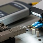
How do I confirm DOM readings are safe for LACP SFP ports?
Record Rx power, Tx bias, temperature, and any DOM alarm flags on each member during a steady traffic window. Then compare deltas across members; if one member sits near alarm thresholds, treat it as a candidate for replacement or fiber cleaning.
What fiber cleanliness checks prevent most LACP SFP issues?
Use an inspection scope to verify end-face contamination on both sides of the connector and clean with validated procedures before re-termination. In many real deployments, dirty LC ends are the dominant cause of intermittent LOS and CRC bursts.
Are there IEEE or standards references relevant to LACP SFP?
LACP is standardized under IEEE 802.1AX, while the optical physical-layer characteristics for Ethernet transceivers are defined by IEEE 802.3 for each speed and reach class. For operational behavior, vendor datasheets and switch CLI documentation for DOM and optics qualification are also critical. IEEE Standards Portal
Where do I find vendor guidance on DOM and supported optics?
Check your switch vendor’s transceiver compatibility list and the transceiver datasheets that describe DOM register behavior and alarm thresholds. Also review platform release notes because DOM handling and optics qualification logic can change between firmware versions. Vendor documentation hub
To deploy LACP SFP optics reliably, treat optics as part of the LAG system: match reach class, validate DOM margins, standardize module identity across members, and troubleshoot with optical and interface counters together. Next, review fiber-transceiver-dom-and-link-budget to build a repeatable pre-install optical testing workflow.
Author bio: I have deployed SFP and SFP+ LAG uplinks in multi-rack data centers, validating DOM alarms and optical link budgets during change windows. I write vendor-aligned runbooks that translate IEEE and datasheet constraints into field-ready acceptance tests.