When a single uplink fails, many networks still experience microbursts, routing reconvergence, or temporary packet loss. This article helps network engineers and field operators design a dual-path SFP redundancy model using LACP fiber optic link aggregation so traffic continues over the surviving path. You will get an implementation checklist, a realistic data center scenario, and troubleshooting steps for the most common failure modes.
Prerequisites for dual-path LACP fiber optic SFP redundancy
Before you touch cabling, confirm the hardware and optics can actually support aggregated links across two independent physical paths. Your goal is active/active forwarding where the switch hashes flows across members, while the control plane remains stable during failures.
Plan around IEEE aggregation behavior and vendor-specific operational details. LACP is defined by IEEE 802.1AX (formerly 802.3ad), and it requires consistent LACP parameters on both ends (system priority, key, and actor/partner settings). If your switches support “MLAG” or “vPC”-style features, decide whether you need them; LACP alone does not eliminate all split-brain risks.
Minimum requirements
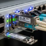
- Switches: Two switches that support IEEE 802.1AX LACP on the same interface type (for example, both ends support SFP/SFP+ ports and LACP on those ports).
- Optics: Compatible SFP transceivers with matching speed and reach (for example, 10G-SR on both ends for 10G Ethernet).
- Two physical paths: Distinct fiber routes, ideally through separate patch panels/trays and separate upstream optics or mux/demux where applicable.
- Same VLAN/L2 policy: The aggregated interface must carry identical VLAN tagging/untagging behavior on both switches.
- Documented cabling map: Port-to-port inventory with serial numbers and DOM readings for each transceiver.
Expected outcome: You can validate that both switch ends will form an LACP bundle and that each member link has a consistent configuration (speed, duplex, VLAN policy) and reliable optical power margins.

Step-by-step implementation: build the dual-path LACP fiber optic bundle
This numbered sequence assumes you are aggregating Ethernet links (not FC or InfiniBand) and using SFP optics. Adjust interface names and command syntax to your platform, but keep the logical intent identical.
Choose the interface type and member count
Pick a single Ethernet speed and optics family for the aggregated interface. For example, if you use 10GBASE-SR, use the same data rate on all members. In most leaf-spine ToR designs, engineers commonly use 2 to 4 LACP members per bundle to balance redundancy and operational simplicity.
Expected outcome: All member ports are the same interface speed and support LACP.
Select optics that match your distance and budget
For short-reach links, 850 nm multimode SR optics are common. For example, a Finisar FTLX8571D3BCL is an SFP+ SR-class device, while Cisco and FS.com offer equivalent SR parts; verify exact reach, encoding (10GBASE-SR), and DOM support if you rely on telemetry. For longer reaches, consider 1310 nm single-mode LR parts, and ensure both ends share the same wavelength and connector type (LC/UPC vs APC where relevant).
| Parameter | 10GBASE-SR (850 nm MM) | 10GBASE-LR (1310 nm SM) | Example part numbers to compare |
|---|---|---|---|
| Nominal wavelength | 850 nm | 1310 nm | Finisar SR/LR equivalents; Cisco/FS.com catalog parts |
| Typical reach | 300 m to 400 m (OM3/OM4 dependent) | 10 km | Vendor datasheet dependent |
| Connector | LC (verify) | LC (verify) | LC/UPC common for SR and SM |
| Tx power class | Varies by vendor; check allowed Rx power | Varies; check optical budget | Use DOM or vendor optical budget tables |
| Data rate | 10.3125 Gbps (10G Ethernet) | 10.3125 Gbps (10G Ethernet) | Must match switch port speed |
| DOM support | Common; verify “digital optical monitoring” | Common; verify DOM | Check DOM compatibility notes in vendor docs |
| Operating temperature | Typically commercial or industrial SKUs | Typically commercial or industrial SKUs | Pick based on ambient conditions |
Expected outcome: Optics are matched by speed, connector, and distance class, with sufficient optical margin verified by DOM readings or planned optical budget.
Wire two independent fiber paths
Route member links through separate patch panels and, where possible, separate fiber trays. Label fibers clearly at both ends. If you reuse the same patch panel but separate fibers, you still reduce the chance that one cut or connector failure drops both members. For true resilience, aim for separation at least at the patching layer.
Expected outcome: A single fiber cut or patch-panel failure should remove only one member link, not the entire bundle.

Configure LACP parameters consistently on both ends
Use the same LACP mode on both switches (active/active is common). Keep the same aggregation key behavior and ensure the bundle name or interface ID is consistent with your platform’s model. If your switches let you tune system priority or timeouts, keep them aligned with vendor guidance.
- Set LACP to active on both ends.
- Set the aggregated interface VLAN tagging policy.
- Ensure member ports are identical in speed and duplex (avoid auto-negotiation mismatches).
- Disable conflicting features on member ports (for example, avoid mixing trunk/access modes between members).
Expected outcome: LACP forms and shows all intended member ports as “in-sync” or “selected,” depending on your vendor terminology.
Validate hashing and failover behavior
After LACP is up, test with controlled traffic flows and verify that traffic continues when you administratively disable one member. Engineers often validate with a traffic generator or by using measurable counters: interface octets, LACP member state transitions, and any platform-specific “bundle” operational status.
Expected outcome: When one member fails, the LACP bundle remains up and traffic shifts to the remaining member with no bundle flap.
Pro Tip: Many operators see “bundle stays up” but still experience latency spikes because their traffic hashing policy is per-flow. If you deploy a single long-lived TCP flow, it may remain pinned to one member until it re-establishes. Plan validation by running multiple concurrent flows across source/destination pairs, not only one session.
Real-world deployment scenario: dual-path SFP in a 3-tier data center
Consider a leaf-spine data center with 48-port 10G ToR switches connecting to two spine switches. Each ToR has two aggregated uplinks using LACP with 4 member links, each populated with 10GBASE-SR SFP+ optics for a ~120 m fiber distance across separate patch panels. VLANs are trunked across the bundle, and the design targets zero downtime during a single connector or patch-panel incident.
In this scenario, engineers monitor optical DOM telemetry (Tx bias current, Rx power) and LACP member states. During maintenance, they disable one member port and confirm that the bundle remains forwarding while the disabled member transitions to “down” without causing an aggregation reformation event. The operational goal is to keep the forwarding plane stable while allowing the control plane to converge quickly.
Expected outcome: A single fiber fault removes only one member, while the LACP bundle stays active and maintains service continuity for active workloads.

Selection criteria and decision checklist for LACP fiber optic
Engineers typically fail first at the selection stage, not the configuration stage. Use this ordered checklist to reduce rework and avoid incompatibility surprises.
- Distance and fiber type: Match SR to OM3/OM4 requirements and SM to your measured link length and connector losses.
- Switch compatibility: Confirm the switch supports the transceiver form factor and speed on the target port (SFP vs SFP+ vs combo).
- Optical budget and DOM behavior: Verify Tx/Rx power margins and whether DOM telemetry is accepted or blocked by the switch.
- Connector and polarity: Ensure LC/UPC vs APC and correct polarity method (MPO vs 2-fiber LC is different).
- LACP configuration constraints: Validate that all member ports can be in the same L2 mode and that the platform allows aggregation of those ports.
- Operating temperature: Choose commercial vs industrial optics based on rack ambient and airflow; cold bays can affect power and bias.
- Vendor lock-in risk: OEM-only SFP policies can increase replacement lead time; third-party compatibility varies by platform.
- Failure domain planning: Physically separate paths so one incident does not take down all members.
Expected outcome: A selected optics and port plan that supports stable LACP aggregation and realistic replacement operations.
Common mistakes and troubleshooting tips for LACP fiber optic bundles
Below are frequent failure modes field teams encounter. Each item includes root cause and an actionable fix.
LACP bundle does not form or stays partially up
Root cause: Member ports are not identical in configuration (trunk/access mode, VLAN allowed list, or speed), or LACP mode differs between ends. Some platforms also require that member ports belong to the same hardware forwarding context.
Solution: Verify that all member ports have the same VLAN tagging behavior and that LACP is active on both sides. Confirm link speed and duplex are forced consistently if your platform allows it. Re-check that the ports are the correct type for LACP aggregation.
Optical errors increase, causing member flaps
Root cause: DOM power values are outside the switch or optics tolerance window due to dirty connectors, exceeded optical budget, or mismatched fiber type (OM3 vs OM4 assumptions). SR modules are especially sensitive to patching losses.
Solution: Clean LC connectors with lint-free wipes and proper cleaning method, then re-seat. Use an optical power meter or switch DOM to verify Rx power is within the vendor’s recommended range. If you see consistent low Rx power, measure end-to-end loss with an OTDR or certified loss tester.
“No downtime” claim fails during a connector incident
Root cause: Both LACP members share the same patch panel, tray, or breakout box, so a single cut or patch-panel outage removes all links. LACP can only protect against failures that affect members independently.
Solution: Reroute one or more member links so each uses a distinct physical failure domain. Update your cable map and verify independence by simulating a failure (for example, disconnect one patch panel uplink).
Hashing imbalance causes congestion on one member
Root cause: Your traffic pattern is dominated by a small number of long-lived flows, and the switch hashes those flows to the same member. This can create “looks healthy but performs poorly” symptoms.
Solution: Validate with multiple concurrent flows. If your platform supports it, review load-balancing criteria (source/destination MAC, IP, TCP/UDP ports). Consider application-level connection distribution or enabling ECMP-like behavior for routed traffic where appropriate.
Cost and ROI considerations for LACP fiber optic redundancy
Costs vary by speed and reach, but engineering teams generally see transceiver unit prices roughly in the range of $40 to $200 per SFP-class module for common 10G SR parts, with OEM-branded optics often higher than third-party equivalents. Total cost of ownership depends on replacement lead time, optics compatibility testing time, and the operational overhead of managing multiple vendor SKUs.
From an ROI perspective, dual-path LACP designs can reduce downtime-related incident costs and shorten maintenance windows. However, there is a real trade-off: more optics means more DOM data to monitor and more components that can fail. Plan spares strategy and compatibility testing before rollout to avoid expensive “swap until it works” troubleshooting.
FAQ
What does LACP fiber optic actually improve?
LACP improves resilience and bandwidth utilization by aggregating multiple physical links into one logical interface. With dual-path cabling, a failure of one member link should not take the entire logical link down.
Can I use different SFP models in the same LACP bundle?
You generally should not. Members must be functionally equivalent at the Ethernet layer (same speed and correct optics class), and vendors may enforce strict requirements for optics parameters and DOM behavior.
How do I confirm DOM readings are safe for link stability?
Check switch-reported DOM telemetry such as Rx power and optical bias current (names vary by vendor). Compare values against the optics datasheet and your switch’s accepted thresholds, and treat out-of-range readings as a maintenance trigger.
Does LACP guarantee zero downtime?
LACP reduces downtime risk by keeping the aggregated interface operational when one member fails. It does not prevent service impact if both members share the same failure domain, if VLAN policy mismatches cause bundle reformation, or if traffic hashing concentrates load.