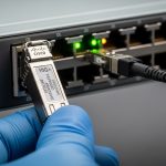
If you have ever racked a new optics module into a QFX switch and watched the link stay down, you know the cost of guessing. This article helps network engineers and IT ops teams validate a Juniper QFX transceiver compatible choice using wavelength, reach, DOM behavior, and operational limits. You will also get a practical checklist for avoiding incompatibility surprises, plus ROI math for OEM versus third-party optics.
Why “compatible” fails: the real compatibility checklist
Juniper QFX optics compatibility is not only about matching the form factor (SFP, QSFP, QSFP28) and data rate (10G, 25G, 40G, 100G). In field deployments, failures usually trace to one of four categories: incorrect optical standard (SR versus LR), DOM or EEPROM readability issues, transceiver temperature or power budget violations, or firmware and port-profile mismatches. IEEE 802.3 defines key electrical and optical behaviors, but vendor implementations can be stricter than the baseline.
In practice, engineers validate before installing by cross-checking the transceiver’s datasheet against the QFX port’s required optics profile, including supported wavelength (for example, 850 nm for SR), fiber type (OM3/OM4), and maximum link distance. If you rely on third-party modules, ensure the vendor provides explicit support for QFX series and that the module exposes DOM fields your switch expects.
For authority on Ethernet optical interfaces and optics parameter norms, consult [Source: IEEE 802.3]. For vendor behavior, rely on the transceiver datasheet and Juniper optics documentation: Juniper Documentation.

Core optics specs that must match QFX port expectations
The fastest way to reduce risk is to treat compatibility as an optics engineering problem. Start with the optical standard and wavelength, then confirm reach assumptions based on fiber attenuation and patch cord losses. For SR optics at 850 nm, the limiting factor is typically modal bandwidth and connector cleanliness; for LR optics at 1310 nm, it is typically fiber attenuation and dispersion margin.
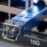
Next, verify electrical interface mapping: the QFX port’s expected lane rate and modulation format must match the transceiver type. For example, 10GBASE-SR uses 10G signaling with multimode optics, while 100G modules can be based on four-lane or eight-lane architectures depending on the form factor and standard. Finally, confirm DOM support: your QFX will query EEPROM and DOM diagnostic thresholds; missing or nonconforming DOM can trigger port disable or link flaps.
| Spec | Example module | What to verify on QFX | Common mismatch |
|---|---|---|---|
| Data rate | 10G SFP+ (e.g., Cisco SFP-10G-SR or Finisar FTLX8571D3BCL) | Port supports 10G optics profile | Module is 1G/2G capable but port profile expects 10G |
| Wavelength | 850 nm SR (multimode) | QFX expects SR at 850 nm | Using 1310 nm LR on an SR-designated port |
| Reach | Up to 300 m on OM3 for typical SR | Budget includes patch cords and splices | Assuming full vendor reach without accounting for loss |
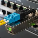
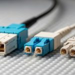
| Connector | LC duplex | Fiber type and polarity match | Wrong polarity or mismatched connector type |
| DOM | Digital optical monitoring | EEPROM readable; DOM thresholds accepted | DOM absent or nonstandard mapping |
| Power and temp | Vendor-defined operating range | Module stays within QFX ambient limits | Overheating in high-density racks |
Real deployment example: verifying SR optics in a leaf-spine QFX fabric
In a 3-tier data center leaf-spine topology with 48-port 10G ToR switches and 10G uplinks, a team replaced 96 aging SR links. Each link used OM4 fiber with two 2 m patch cords and one 0.5 dB/m run; total worst-case attenuation was budgeted at about 1.6 dB per direction including connectors. They installed modules labeled for 10GBASE-SR and confirmed DOM readout via switch show commands immediately after insertion, then validated link stability over a 24-hour monitoring window.
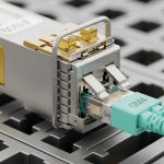
Operationally, the team also standardized on known compatible part numbers and kept a small “known-good” inventory on-site. When a single link remained down, the root cause was not the transceiver; it was a swapped patch cord polarity and a dirty LC face that produced intermittent receive power. After cleaning with approved inspection and cleaning tools, the link came up without replacing optics.

Decision checklist for a Juniper QFX transceiver compatible purchase
Use this ordered checklist before ordering or deploying a new optics batch. It is designed to maximize uptime and minimize rework after installation.
- Distance and fiber type: confirm OM3 versus OM4, connector loss, and splice/patch cord budget.
- Optical standard: SR versus LR versus ER, plus wavelength (for example, 850 nm for SR).
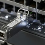
- Form factor and speed: SFP, SFP+, QSFP+, QSFP28, or CFP2, aligned to the QFX port.
- DOM behavior: ensure the module exposes standard DOM fields and vendor states QFX compatibility.
- Operating temperature: compare module range to your rack ambient and airflow pattern.
- Switch compatibility and firmware: verify the QFX software version supports that optics profile.
- Vendor lock-in risk: test one module first, then standardize; avoid mixed unknown batches.
Pro Tip: In the field, “link up but with errors” often indicates an optical budget or polarity problem rather than an incompatibility issue. Measure receive power with the switch DOM and correlate it to your expected attenuation; if RX is consistently near the vendor’s sensitivity edge, you will see CRCs and drops long before the link fully fails.
Common mistakes and troubleshooting patterns
1) Wrong optics standard with a matching data rate
Root cause: the module is SR-capable at the correct speed but the wavelength/standard is wrong (for example, LR at 1310 nm used where SR at 850 nm was expected).
Solution: verify wavelength and fiber type against the QFX port optics profile; replace with the correct SR or LR module type.
2) DOM not readable or nonstandard diagnostics
Root cause: third-party modules with incomplete EEPROM mapping can cause port events, link flaps, or missing diagnostics.
Solution: test a single module in the exact QFX model/firmware; require DOM support in the vendor datasheet and keep a known-good OEM module for rollback.
3) Overlooked optical budget and connector cleanliness
Root cause: patch cord loss, dirty LC faces, or a polarity swap can push RX power below sensitivity margin.
Solution: inspect and clean connectors with proper tools, confirm polarity, and re-check attenuation with an OTDR or loss meter where possible.
4) Thermal stress in high-density racks
Root cause: inadequate airflow or high ambient can drive the module beyond safe operating temperature, leading to throttling or intermittent failures.
Solution: measure ambient near the cage, verify fan tray operation, and consider higher-spec modules with documented temperature headroom.
Cost and ROI: OEM versus third-party optics on QFX
Pricing varies by speed and reach, but realistic procurement ranges for common optics often look like: 10G SR SFP+ modules can be roughly $30 to $120 each; 25G SR SFP28 modules may range higher; 100G optics typically cost more per port. OEM optics usually carry higher unit price but may reduce field failures and shorten troubleshooting time. Third-party modules can cut capex, but the ROI depends on your change-management discipline and your ability to test and standardize part numbers.
TCO should include labor time for verification, downtime risk during replacements, and the cost of repeat truck rolls. In one common pattern, a team that standardizes on a single third-party vendor and tests compatibility upfront can reduce module spend, but they still keep a small OEM reserve to resolve edge cases quickly. The most measurable ROI lever is reducing mean time to repair by ensuring DOM readability and predictable behavior on QFX.

FAQ
How do I confirm a Juniper QFX transceiver compatible module before installing it?
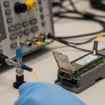
Verify form factor, data rate, wavelength, reach, and DOM support against both the module datasheet and Juniper port requirements. Then test one unit in the target QFX model and software version, checking that DOM fields populate and link stays stable under monitoring.
Can I use third-party optics on a QFX switch?
Often yes, but compatibility is not guaranteed by speed alone. Choose vendors that explicitly document QFX compatibility and provide DOM behavior details; validate with a pilot deployment before ordering in bulk.
What causes link up but frequent CRC or packet drops?
Common causes are insufficient optical budget, dirty or damaged connectors, and polarity swaps. Use DOM receive power and error counters to distinguish an optics margin issue from a misconfiguration or cabling problem.
Do DOM diagnostics matter for compatibility?
They matter because QFX relies on EEPROM and DOM data to expose diagnostics and sometimes to enforce operational thresholds. Missing or nonstandard DOM behavior can lead to port instability or lack of visibility.
Which is safer for reliability: OEM or compatible third-party optics?
OEM typically reduces risk of edge-case incompatibilities and speeds troubleshooting when support is involved. If you choose third-party, mitigate risk with part-number standardization, DOM validation, and a known-good replacement plan.
Where can I find authoritative guidance for optics and Ethernet requirements?
Use IEEE 802.3 for baseline Ethernet optical interface norms and consult Juniper documentation for platform-specific expectations. Also rely on transceiver datasheets for wavelength, reach, DOM, and temperature specs: [[EXT:https://standards.ieee.org|