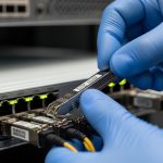
In a live Juniper EX deployment, the wrong transceiver can mean link flaps, unsupported optics, or a costly truck roll. This article helps network operators and field engineers choose the right Juniper EX transceiver across 1G, 10G, 25G, 40G, and 100G speeds, using a practical, operations-first checklist. You will get eight top options, the key specs that matter, and troubleshooting patterns pulled from real-world bring-up and maintenance workflows.
Top 8 Juniper EX transceiver options engineers actually stock
Rather than guessing by speed alone, treat optics as a compatibility problem: electrical lane behavior, fiber type, reach class, and DOM telemetry support all interact with the EX line card and optics cage. Below are eight “stockable” choices that map cleanly to common EX leaf-spine, aggregation, and campus designs. For each item, you will see where it fits best, what it typically replaces, and the operational pros and cons.
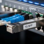
1G: 1000BASE-SX for legacy access and short MM links
Best fit scenario: Older access blocks and service appliances where you need 1G over multimode fiber (MMF) with short reach. In practice, this often means 150 to 550 m depending on link budget, patch cord quality, and OM3 vs OM4.
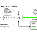
Key specs/details: 1GBASE-SX optics typically use 850 nm and LC connectors. Ensure the EX port supports SFP/SFP-like optics in that speed profile and that DOM (digital optical monitoring) is compatible for your NMS alarms.
Pros: Low cost, widely available, simple MMF cabling reuse. Cons: Reach is limited vs single-mode; MMF plant quality still matters.
10G: 10GBASE-SR for most MMF data center runs
Best fit scenario: A 3-tier data center leaf-spine topology where each ToR aggregates to spines over 100 to 300 m MMF. Teams often deploy SR to avoid the operational burden of single-mode optics in the middle of the fabric.
Key specs/details: 10GBASE-SR uses 850 nm with LC. Popular third-party optics include models sold for EX compatibility; examples you may encounter in audits include Finisar and FS.com SR optics, but always validate against Juniper’s supported optics list for your exact EX model and port type.
Pros: Best cost-per-port on MMF; easy operational swaps. Cons: Not ideal for longer campus runs; MMF budgeting and cleaning become critical.

10G: 10GBASE-LR for single-mode reach and WAN-adjacent links
Best fit scenario: Campus distribution blocks or edge interconnects where spares are shared between EX and other chassis. LR is common when you need 10 km class reach on single-mode fiber (SMF).
Key specs/details: 10GBASE-LR uses 1310 nm and LC. Verify that your EX port supports the specific optics form factor (SFP+ vs XFP-like where applicable) and that the transceiver’s DOM alarms map cleanly to your monitoring stack.
Pros: Longer reach; less sensitive to MMF plant aging. Cons: Higher optics cost; requires SMF handling discipline.
25G: 25GBASE-SR for modern leaf-spine density
Best fit scenario: Upgrades where you increase throughput without changing the fiber plant. Many operators move to 25G over MMF for ToR-to-aggregation links, especially with OM4.
Key specs/details: 25GBASE-SR uses ~850 nm and LC. Operationally, lane-to-lane signal quality and patch cord insertion loss can become the limiting factor as you scale density.
Pros: Good balance of bandwidth and cost; leverages existing MMF. Cons: More stringent link budgets than 10G-SR; cleaning and testing matter more.
40G: 40GBASE-SR for fanout consolidation
Best fit scenario: Consolidating multiple 10G circuits into fewer uplinks. In practice, teams use SR when they have MMF runs on the order of a few hundred meters and want to reduce switch port count.
Key specs/details: 40GBASE-SR typically uses 850 nm with MPO/MTP or LC variants depending on transceiver type. Confirm the EX cage geometry and optics keying to avoid physical mismatch.
Pros: Port consolidation; strong performance in MMF data centers. Cons: MPO/MTP handling is error-prone; polarity and cleanliness issues are common.

40G: 40GBASE-LR4 for SMF backbone sections
Best fit scenario: Backbone segments on SMF where you need 10 km class reach and can tolerate higher per-port cost. LR4 is often used when the operator wants predictable reach without upgrading to 100G immediately.
Key specs/details: LR4 uses ~1310 nm with multiple wavelengths aggregated. Confirm that the EX port supports the transceiver type and that your fiber plant has acceptable chromatic dispersion characteristics for LR4 class optics.
Pros: Longer reach; stable for SMF. Cons: Higher cost; requires strict SMF performance and connector hygiene.
100G: 100GBASE-SR4 for high-density MMF fabrics
Best fit scenario: Modern fabrics where you want 100G between leaves and spines over MMF. This is common when OM4 is available and you need to keep transceiver count and rack power manageable.
Key specs/details: 100GBASE-SR4 typically uses ~850 nm and an MPO-12 interface. Power draw is generally higher than 25G, so check your chassis optics power budget and airflow assumptions.
Pros: High bandwidth without SMF conversion; scalable density. Cons: MPO polarity and patch cord length rules are unforgiving; budget is tight.
100G: 100GBASE-LR4 for SMF reach where MMF is not an option
Best fit scenario: Inter-building links on SMF where you need 100G class reach and want a single-mode-friendly optic. This is the “bridge” option when you cannot rely on OM4 availability end-to-end.
Key specs/details: LR4 uses ~1310 nm optics and MPO-like interfaces depending on the transceiver. Validate link distance, dispersion tolerance, and your fiber attenuation at the relevant wavelengths.
Pros: Strong reach; compatible with SMF backbone practices. Cons: Typically expensive; optics availability and vendor lead times can affect maintenance windows.
Key specs comparison: wavelength, reach, interface, and operating limits
Engineers win by matching optics to the fiber plant and the EX port optics type, not by chasing a single “reach number.” Use the table below as a fast screening tool before you consult the EX optics compatibility list.
| Transceiver class (typical) | Wavelength | Target reach (typical) | Connector / interface | Data rate | Operating temperature (typical) |
|---|---|---|---|---|---|
| 1000BASE-SX | 850 nm | ~150 m to ~550 m (MMF class dependent) | LC | 1G | -5 C to 70 C (varies by vendor) |
| 10GBASE-SR | 850 nm | ~300 m to ~400 m (MMF class dependent) | LC | 10G | -5 C to 70 C (varies by vendor) |
| 10GBASE-LR | 1310 nm | ~10 km (SMF) | LC | 10G | -5 C to 70 C (varies by vendor) |
| 25GBASE-SR | ~850 nm | ~70 m to ~300 m (MMF class dependent) | LC | 25G | -5 C to 70 C (varies by vendor) |
| 40GBASE-SR | ~850 nm | ~100 m to ~150 m (MMF class dependent) | MPO/MTP (often) | 40G | -5 C to 70 C (varies by vendor) |
| 40GBASE-LR4 | ~1310 nm | ~10 km (SMF) | LC or MPO variant (check) | 40G | -5 C to 70 C (varies by vendor) |
| 100GBASE-SR4 | ~850 nm | ~100 m to ~150 m (MMF class dependent) | MPO-12 | 100G | -5 C to 70 C (varies by vendor) |
| 100GBASE-LR4 | ~1310 nm | ~10 km (SMF, class dependent) | MPO-12 variant (check) | 100G | -5 C to 70 C (varies by vendor) |
Standards anchor: Ethernet optical physical layers are defined in IEEE 802.3 clauses for each speed and reach family. For engineering alignment, refer to IEEE 802.3 for baseline electrical and optical behavior. [Source: IEEE 802.3]. For transceiver-specific DOM behavior and electrical interfaces, consult vendor datasheets and the optics compliance guidance from your switch vendor. [Source: Juniper Networks transceiver documentation].
Selection criteria checklist for a safe EX optics purchase
When procurement and field teams disagree, it is usually because they optimized different variables. Below is the ordered decision checklist that reduces surprises during install and RMA.
- Distance and fiber type: verify OM3 vs OM4 vs SMF, then