If your Juniper EX switch ports refuse to link, it is usually not the switch. It is the optics: wrong wavelength, incompatible vendor timing, missing DOM support, or simply exceeding the fiber budget. This article helps network engineers, field techs, and procurement leads choose the right Juniper EX transceiver across 1G to 100G, with practical deployment details and a short decision checklist.
Top 1: The 1G SFP era, still alive in access and aggregation
For older wiring closets, most engineers start with 1G SFP optics: common in access switches and some aggregation tiers. You typically see 1310 nm for single-mode links and 850 nm for multi-mode, aligned with IEEE 802.3z and vendor datasheets. Best-fit scenario: a campus access layer where you need up to 10 km single-mode or short multi-mode patching.
Key specs to check: data rate (1.25G), wavelength (850/1310), connector type (LC), and temperature rating (often 0 to 70 C for standard, wider for extended). DOM support matters for EX series monitoring; if you want temperature and laser bias visibility, pick modules with digital optical monitoring.
- Pros: cheap per port, widely supported, easy spares.
- Cons: limited reach versus 10G/25G; older optics can be pickier about link partners.

Top 2: 10G SFP+ optics for leaf-spine and edge uplinks
When you move from access to higher throughput, 10G SFP+ becomes the workhorse. On Juniper EX, you will commonly choose SR (multi-mode, usually 850 nm) for short reach, or LR (single-mode, 1310 nm) for longer runs. IEEE 802.3ae covers 10GBASE-SR/LR behavior.
Best-fit scenario: a 3-tier data center leaf-spine with 48-port 10G ToR switches, where leaf uplinks run over OM3/OM4 multi-mode to aggregation at 300 m to 400 m. SR optics reduce cost and simplify cabling, as long as your fiber plant is clean and meets modal bandwidth requirements.
| Module class | Typical part family | Wavelength | Connector | Reach (typical) | DOM | Operating temp |
|---|---|---|---|---|---|---|
| 1G SFP | SFP-1G-SX or SFP-1G-LX | 850 / 1310 nm | LC | 550 m (MM) / 10 km (SM) | Optional | 0 to 70 C |
| 10G SFP+ | SR or LR | 850 / 1310 nm | LC | 300 m (MM) / 10 km (SM) | Common | 0 to 70 C |
| 25G SFP28 | SR / LR | 850 / 1310 nm | LC | 100 m (MM) / 10 km (SM) | Common | 0 to 70 C |
| 40G QSFP+ | SR4 or LR4 | 850 / 1310 nm | LC | 100 m (MM) / 40 km (SM) | Common | 0 to 70 C |
| 100G QSFP28 | SR4 / LR4 / ER4 | 850 / 1310 / 1550 nm | LC | 70 m (MM) / 10 km (SM) | Common | 0 to 70 C |
- Pros: mature ecosystem; predictable behavior.
- Cons: multi-mode reach depends heavily on OM grade and cleaning.
Top 3: 25G SFP28 for the “upgrade without replacing everything” phase
25G SFP28 is the practical middle child: faster than 10G without forcing a full 100G rewrite. Typical wavelengths include 850 nm for SR on multi-mode and 1310 nm for LR on single-mode. Many EX deployments adopt 25G to refresh uplinks while keeping existing switch line cards and rack designs.
Best-fit scenario: a modernizing enterprise where you have 10G access and want 25G uplinks to aggregation. You run OM4 multi-mode for ~100 m and keep single-mode for longer campus hops. Ensure your patch cords are short and your MPO/MTP cleaning standards are not “good enough.”
- Pros: strong ROI for phased migrations.
- Cons: SR reach shrinks quickly if your optics or fiber plant is marginal.
Top 4: 40G QSFP+ for high-density aggregation and older spine uplinks
40G QSFP+ is common where you already have multi-lane optics infrastructure and want to consolidate uplinks. You will see SR4 (850 nm) and LR4 (often 1310 nm), typically using four lanes per direction. IEEE 802.3ba addresses 40GBASE-SR4 and related behaviors.
Best-fit scenario: a regional aggregation node with 8 to 16 high-capacity uplinks, where cabling is already laid out for four-lane optics using OM3/OM4. You gain port density and reduce switch-to-switch port count, which can be a budget win for line card port licensing or optics spares.
- Pros: better density than 10G fan-out.
- Cons: multi-mode SR4 distance depends on fiber and lane balance; MPO cleaning is mandatory.
Top 5: 100G QSFP28 for spine scale, with reach budgeting done like adults
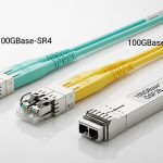
At 100G, optics choices become more about link budgets than “it should work.” You typically choose SR4 (850 nm) for short multi-mode, LR4 (1310 nm) for moderate single-mode, or ER4 for longer single-mode distances. Juniper EX platforms can support 100G with QSFP28 ports depending on model and optics compatibility lists.
Best-fit scenario: a spine layer in a data center with 8 x 100G uplinks per rack. You run single-mode between rows at 2 to 10 km, with conservative assumptions for patching loss and connector reflectance. Buy in bulk, but do not skip DOM validation and vendor compatibility checks.
- Pros: fewer ports, lower operational complexity at scale.
- Cons: higher module cost; failures are rarer but more expensive.

Pro Tip: If your Juniper EX shows “link up” but you see intermittent CRC errors, treat it like a fiber quality problem first. In the field, the most common cause is microscopic contamination or an over-aggressive bend radius, not the transceiver. Clean, scope, and measure insertion loss before you RMA perfectly good optics.
Top 6: Compatibility and DOM support that prevents the “mystery link” problem
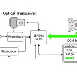
Juniper EX optics behavior can hinge on DOM presence, vendor EEPROM implementation, and the switch’s transceiver acceptance rules. If you rely on monitoring (laser bias, received power, temperature), confirm that the module provides DOM data in the expected format. Also verify the module is the correct physical form factor: SFP vs SFP+ vs SFP28 vs QSFP+ vs QSFP28.
Best-fit scenario: multi-vendor environments where you stock spares. You want consistent telemetry so your NOC can correlate optical alarms with incident timelines. When procurement mixes OEM and third-party modules, align on DOM support and verify in staging before broad rollout.
- Pros: better observability, faster troubleshooting.
- Cons: third-party modules may report DOM data differently; some platforms may be stricter.
Top 7: Selection criteria checklist engineers actually use
Use this ordered checklist to avoid the “wrong optic, right port” circus.
- Distance and fiber type: SM vs MM; confirm OM3/OM4 if using SR optics.
- Wavelength and link class: match SR4/LR4/SR/LR to the planned topology.
- Switch compatibility: validate against the specific Juniper EX model and optics support matrix.
- DOM requirements: decide if you need temperature and power telemetry for alarms.
- Operating temperature: verify extended temp if the rack has hot spots.
- Vendor lock-in risk: weigh OEM part pricing versus third-party availability and RMA terms.
For authoritative baseline behavior, reference IEEE Ethernet optics definitions and vendor datasheets: [Source: IEEE 802.3 standard], [Source: Juniper hardware documentation], [Source: vendor transceiver datasheets].
Top 8: Common mistakes and troubleshooting wins
Here are the failure modes that waste the most time on real tickets.
- Mistake 1: Picking SR when the fiber run is longer than expected
Root cause: OM3/OM4 bandwidth limits, patch cord loss, and connector count reduce effective reach.
Solution: measure with an optical power meter, confirm insertion loss, and choose LR/ER optics if the budget is tight. - Mistake 2: Dirty fiber endfaces with “it worked yesterday” behavior
Root cause: contamination changes with handling and temperature; multi-lane optics are unforgiving.
Solution: clean with approved methods and inspect with a fiber scope before reseating. Replace patch cords if scratches are visible. - Mistake 3: DOM mismatch expectations
Root cause: third-party optics may not provide complete DOM telemetry, or the switch may treat it as non-standard.
Solution: confirm DOM support during qualification; if monitoring is required, standardize on a vetted vendor list. - Mistake 4: Wrong optics form factor or lane type
Root cause: SFP vs SFP+ vs QSFP28 confusion, or SR4 vs LR4 used