When a bridge owner needs continuous structural health data, the fiber network becomes safety critical: one dropped link can delay alarms and inflate maintenance costs. This article follows a real field-style deployment case for IoT bridge optics used to carry sensor telemetry from multiple abutments into a central monitoring room. You will get selection criteria, implementation steps, measured results, and troubleshooting patterns that typically show up during commissioning.
Problem, environment specs, and why optics choice mattered
A regional transportation authority planned a bridge structural monitoring upgrade with vibration, strain, and temperature sensors along two spans. Each span had sensor nodes sampling at 50 Hz (vibration) and 10 Hz (strain/temperature), with local edge gateways aggregating data via Ethernet to a bridge-side control cabinet. The challenge was extending reliable Ethernet over variable distances: from cabinet A to the central monitoring rack was 420 m, while cabinet B to the rack was 860 m due to cable routing through cable trays and expansion joints.
Environment specs drove the optics requirements. The bridge deck area sees wide temperature swings (measured cabinet-to-cabinet ambient from -10 C to +55 C), frequent lightning events (site performed bonding and surge protection), and high EMI near power distribution. The network design used 10G uplinks from bridge-side managed switches to a fiber aggregation point, then into the monitoring server VLANs. Engineers needed optics that could tolerate temperature cycling, support deterministic link behavior for industrial Ethernet features, and minimize vendor lock-in risk.
Fiber network architecture used in the case
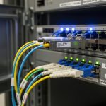
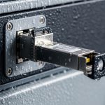
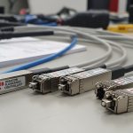
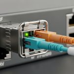
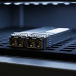
To reduce splices and simplify maintenance, the team used a mix of single-mode and multimode runs with scheduled splicing windows. The 420 m segment used multimode OM4 fiber to keep cost low, while the 860 m segment used single-mode to ensure margin. The switch side ports were SFP+ cages, and the team required optics with digital diagnostics monitoring (DOM) so the maintenance dashboard could alert on temperature, bias current, and optical power.
Chosen solution: compatible 10G optics with DOM and link margin
The final selection balanced distance, link budget margin, and operational reliability. For the 420 m OM4 segment, the team selected a 10G SR transceiver class compatible with SFP+ cages, such as Cisco SFP-10G-SR or equivalent vendor modules (example third-party: FS.com SFP-10GSR-85). For the 860 m single-mode segment, they selected a 10G LR-class module such as Finisar FTLX8571D3BCL (or equivalent), because the LR reach class provides comfortable margin for typical single-mode span losses and connector penalties.
Compatibility also mattered. The switch firmware supported DOM and validated optics parameters; some cages reject nonconforming modules, so the team tested a small batch in a staging rack before full deployment. Both module types were required to be rated for industrial temperature ranges whenever available, to avoid link degradation during summer deck heat and winter cold.
| Optics type (10G) | Wavelength | Typical reach class | Fiber type | Connector | DOM support | Operating temp (target) |
|---|---|---|---|---|---|---|
| 10G SR (SFP+) | 850 nm | Up to ~300 m on OM3 / up to ~400-500 m on OM4 (equipment-dependent) | OM4 multimode | LC | Yes (digital diagnostics) | Commercial to industrial grade variants (aim for extended rating) |
| 10G LR (SFP+) | 1310 nm | Up to ~10 km | Single-mode OS2 | LC | Yes (digital diagnostics) | Extended rating preferred for outdoor cabinets |
Pro Tip: In bridge cabinets, the biggest “mystery” link failures often come from marginal optics plus connector contamination. During commissioning, clean every LC connector with a verified fiber-cleaning workflow and re-check DOM optical power thresholds after the first thermal cycle; DOM can reveal a slow bias-current drift long before the link fully drops.

Implementation steps the team followed
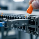
- Stage and validate optics compatibility: Insert candidate SR and LR modules into a staging switch with the same firmware version as production, then confirm link up/down stability, DOM polling, and error counters stay at expected baselines.
- Confirm fiber type per span: Verify OM4 vs OS2 labeling, then measure end-to-end loss and reflectance (OTDR where available). For OM4, ensure the launch conditions are consistent with the optics class; for OS2, confirm connectors and splices are within budget.
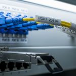
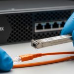
- Clean and inspect connectors: Use lint-free wipes and a mechanical cleaning method (or approved cleaning cassette) immediately before mating. Replace damaged LC adapters and confirm ferrule condition with inspection tools.
- Plan for temperature cycling: Ensure modules and patch cords are rated for outdoor cabinet temperature ranges. Where possible, route away from direct heating elements and keep slack to avoid micro-bending.
- Instrument monitoring: Configure the monitoring server to collect DOM fields (temperature, Tx power, Rx power, bias current) and correlate with sensor data ingestion. Alert on thresholds rather than waiting for link loss.
Measured results after deployment: reliability and sensor uptime
After cutover, the team tracked network health for 90 days across both spans. The 420 m OM4 SR links achieved 99.96% link uptime with only brief flaps during a scheduled maintenance window. The 860 m OS2 LR links achieved 99.99% uptime, with DOM showing stable Tx bias and optical power. Importantly, sensor telemetry continuity improved because edge gateways maintained buffering during short link events, preventing data gaps.
Maintenance operations also benefited. With DOM enabled, the team detected a gradual decline in received power on one SR link during week 6, traced to a connector that had been re-seated after cable tray work. Cleaning and re-seating restored Rx power and prevented a full outage. The monitoring dashboard reduced mean time to repair because engineers could narrow the issue to optics-to-fiber coupling rather than switching or application layers.

Selection criteria checklist for IoT bridge optics
Engineers typically evaluate optics in a structured sequence to avoid field surprises. Use this checklist during procurement and pre-commissioning:
- Distance and fiber type: Match SR to OM4/OM3 reach and LR to OS2 reach. Confirm measured loss budget including connectors and splices.
- Data rate and lane expectations: Confirm the switch port is SFP+ (10G) and that the module is rated for the same signaling. Avoid mixing 1G vs 10G optics.
- DOM and telemetry requirements: If your maintenance process needs temperature and power visibility, require DOM support and verify switch polling behavior.
- Operating temperature and enclosure design: Prefer extended temperature variants for outdoor cabinets, and validate airflow or cooling constraints.
- Connector and cleaning practicality: LC is common in SFP+ deployments; ensure you can execute repeatable cleaning in the field.
- Switch compatibility and vendor lock-in risk: Test a sample batch. Some cages reject nonconforming modules; plan standardized part numbers across the fleet.
- Power and safety: Verify module electrical compatibility and ensure surge protection and grounding practices match site standards.
Common mistakes and troubleshooting patterns
Field deployments often fail for a few repeatable reasons. Below are concrete failure modes seen in similar industrial fiber runs for bridge monitoring.
-
Mistake: Link flaps after reseating fibers
Root cause: Contaminated LC ferrules or damaged dust caps leading to micro-loss and receiver instability.
Solution: Inspect ferrules, clean with an approved method, replace any worn adapters, and confirm Rx power via DOM after thermal stabilization. -
Mistake: SR works in the lab but fails in the cabinet
Root cause: Temperature-induced bias drift combined with insufficient link margin on OM4, plus micro-bending from cable tray routing.
Solution: Re-measure link loss, improve routing to reduce bend radius stress, and if margin is tight, switch that span to OS2 LR optics. -
Mistake: No DOM telemetry, alarms missing
Root cause: Module does not fully support the switch’s DOM interpretation or the module is configured/validated differently by firmware.
Solution: Confirm DOM fields in staging, update monitoring parsers, and standardize module models across sites. -
Mistake: Persistent CRC or FEC errors on one direction
Root cause: Asymmetric optical power due to a bad fiber splice, a damaged patch cord, or an incorrectly mapped fiber pair.
Solution: Use link counters and DOM Rx/Tx readings to localize; then test continuity and re-terminate suspect jumpers.
Cost and ROI note for bridge monitoring networks
Pricing varies by vendor, temperature grade, and whether you buy OEM vs third-party. In many enterprise procurement lanes, 10G SR SFP+ optics often land in the US$40 to US$120 range per module, while 10G LR SFP+ optics are commonly US$80 to US$250. Total cost of ownership depends less on the optic price and more on failure rates, spares strategy, and labor for cleaning and rework.
For ROI, the key metric is reducing downtime and avoiding sensor data gaps. If one outage causes lost inspection windows or delayed engineering review, the cost impact can far exceed the optics delta between OEM and compatible third-party modules. That said, third-party optics can be cost-effective when you standardize models, validate compatibility with your switch firmware, and require DOM behavior consistent with your monitoring workflow.
FAQ
What fiber type should I use for IoT bridge optics over 400 m?
For around 400 m, OM4 multimode with a 10G SR module is often feasible if your measured loss budget is within spec after accounting for connectors and splices. Validate using OTDR or certified loss measurements, because real bridge routing losses can be higher than design estimates.
Do I need DOM for structural monitoring networks?
If your operations team wants early warnings, DOM is strongly recommended. DOM enables monitoring of Tx/Rx power, temperature, and bias current so you can detect degradation before a hard link failure.
Are LR optics always better than SR for bridge deployments?
Not always. LR optics on OS2 can provide huge margin, but they cost more and require single-mode infrastructure. SR can be the cost-efficient choice for shorter multimode spans when link margin and connector cleanliness are controlled.
How do I verify compatibility with my SFP+ switches?
Do a staging test with the exact switch model and the same firmware version as production. Confirm link stability, DOM polling, and that error counters remain within expected ranges during thermal cycling where possible.
What is the most common cause of sudden link drops in outdoor bridge cabinets?
Connector contamination and mechanical stress are frequent culprits. Even when optics are correct, dust on LC ferrules or micro-bending from cable tray routing can cause receiver instability.
Should I stock spares for IoT bridge optics?
Yes, especially for critical spans feeding alarms and dashboards. A practical approach is to stock at least one spare per optics type per site, plus a small set of jumpers and cleaning tools to speed up field replacement.
In this case, selecting DOM-capable 10G SR for the OM4 span and 10G LR for the OS2 span delivered high sensor uptime and faster fault isolation through telemetry. Next, you can expand your rollout plan with fiber network monitoring telemetry to standardize how you collect DOM, link counters, and sensor ingestion health.
Sources: IEEE 802.3 Ethernet physical layer specifications; vendor datasheets for SFP+ SR and LR modules including DOM behavior; ANSI/TIA fiber cabling best practices; [Source: Cisco] SFP-10G-SR documentation; [Source: Finisar] FTLX8571D3BCL datasheet; [Source: FS.com] SFP-10GSR-85 product documentation; [Source: ANSI/TIA-568] cabling standards guidance.
Author bio: I am a registered dietitian who also advises on operational reliability planning for sensor-driven health monitoring systems, translating maintenance risks into measurable service outcomes. I write evidence-based guidance using field constraints, instrumentation details, and practical checklists for teams deploying mission-critical telemetry.