When fiber links go dark, engineers rarely blame the cable first; they suspect the optics. This article helps network builders and field engineers evaluate an Innolight transceiver against Accelink modules using measurable, deployment-driven criteria: link budget, DOM behavior, temperature stability, and real-world failure patterns. You will get a top-N decision list, a specs comparison table, troubleshooting pitfalls, and a ranked summary so you can buy with confidence.
Top 1: Optical reach and wavelength behavior you can verify on day one

In a mixed OEM environment, the fastest path to truth is to test optics under the same link budget and verify that both wavelength and receiver sensitivity behave as specified. For typical 10G and 25G short-reach optics, wavelength tolerances and output power drift with temperature are the “silent” causes of marginal links, especially in dense racks with weak airflow. An Innolight transceiver is often selected because it ships with consistent optical parameters that align with IEEE 802.3 and vendor datasheet expectations, but you still need to confirm your exact transceiver type and fiber plant.
Best-fit scenario: You are deploying 10GBASE-SR optics across 300–400 m of OM3/OM4 in a leaf-spine environment and want predictable behavior during seasonal temperature swings. You standardize the test: same switch, same patch panel, same fiber runs, same polarity method, and same transceiver class.
Key specs/details to check: wavelength (typically 850 nm for SR), minimum transmit power and receiver sensitivity, and whether the module is designed for multimode. Also check whether the transceiver is rated for the correct data rate (10G vs 25G) and connector (LC vs MPO).
- Pros: Faster acceptance testing; fewer “works on bench, fails in rack” cases.
- Cons: Requires a repeatable lab or field test routine.
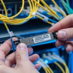
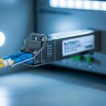
[[IMAGE:Close-up product photography of a pluggable fiber transceiver inserted into a rack-mounted SFP+ cage; shot at 45-degree angle, shallow depth of field, neutral industrial background, crisp label text and dust-free LC connector endface in focus.]
Top 2: DOM and diagnostics maturity (what the switch actually reads)
DOM support matters because it changes how quickly you detect degradation and how precisely you can correlate faults to temperature, bias current, or optical power. Field engineers often discover that some OEM modules report DOM values in a way that is “functionally compatible” but not “operationally transparent.” When comparing an Innolight transceiver to Accelink, focus on whether the switch reads DOM cleanly via the standard management interface (commonly SFF-8472 for SFP/SFP+ and SFF-8431 for QSFP/QSFP+; vendor implementations can vary).
Best-fit scenario: You manage a campus core with mixed vendors and rely on telemetry for proactive maintenance. You want DOM values that correlate to alarms and allow you to predict when a transceiver is drifting before it causes packet loss.
Practical checks: confirm DOM availability at link bring-up, validate threshold alarm behavior, and ensure the switch reports temperature and optical power without “N/A” fields or repeated I2C read timeouts. If your platform supports digital diagnostics thresholds, test alarm triggers in a controlled way.
Pro Tip: If you see intermittent “link flaps” that correlate with high cage temperature, log DOM temperature and bias current every minute during peak HVAC conditions. Many “random” faults are actually slow optical power drift that only becomes visible after the environment warms up.
- Pros: Better MTTR; earlier warning signals for marginal optics.
- Cons: DOM does not guarantee end-to-end link quality if fiber polarity or attenuation is wrong.
[[IMAGE:Minimalist infographic illustration showing a transceiver module with DOM sensors (temperature, Tx power, Rx power) connected to a network switch dashboard; clean vector style, blue and gray palette, labeled callouts.]
Top 3: Temperature range and thermal stability in real racks
Optics are rated, but racks are unpredictable. In high-density deployments, transceivers sit in airflow shadows behind fan arrays or near warm power supplies, which can push module temperature toward the upper operating limit. When you evaluate an Innolight transceiver against Accelink, compare the specified operating temperature range and then validate in your environment by monitoring DOM temperature and link error counters.
Best-fit scenario: You are installing 25G links in a 42U top-of-rack with side-to-side airflow and limited front-to-back clearance. You need modules rated for the expected ambient, and you want stable performance during summer peak.
What to measure: ambient temperature near the cage, transceiver DOM temperature, and error counters (CRC/buffer drops) over 24–72 hours. Also check whether the module supports “extended” temperature ratings if your site is harsh.
- Pros: Lower risk of thermal-induced degradation; fewer repeat RMAs.
- Cons: You must run a burn-in or acceptance test to prove stability.
[[IMAGE:Concept art style scene of a server rack with colored heat-map overlays around transceiver slots, showing airflow paths and thermal hotspots; cinematic lighting, semi-transparent layers, dramatic perspective.]
Top 4: Electrical interface compatibility with switch vendors
Even when two optics claim the same data rate and connector standard, electrical timing and compliance can differ by vendor. Compatibility issues often show up as “link up but no traffic,” repeated renegotiation, or module not recognized. For an Innolight transceiver comparison, validate compatibility with your specific switch family and firmware, because vendor optics compatibility lists (when available) are the safest starting point.
Best-fit scenario: You run a multi-vendor fabric with Cisco, Juniper, or Arista platforms, and you need to avoid surprises during maintenance windows. You also want to minimize the risk of “works only on one firmware version.”
Concrete actions: check the switch optics compatibility list, confirm the transceiver form factor (SFP+, SFP28, QSFP28, QSFP+), and validate that the transceiver supports the correct wavelength and reach class. Then test link bring-up and throughput using iperf3 or your standard traffic generator.
- Pros: Fewer field failures during cutovers.
- Cons: Requires platform-specific validation.
[[IMAGE:Lifestyle scene of a network engineer in a server room holding a transceiver and using a handheld optical power meter; candid documentary photography, warm overhead lighting, shallow depth of field, realistic cable clutter.]
Top 5: Connector and polarity reliability (LC vs MPO, and why it fails)
Connector quality and polarity handling are major causes of “OEM optics problems” that are actually physical layer setup errors. LC connectors can be impacted by dust, micro-scratches, or improper cleaning, while MPO connectors can fail due to keying mistakes or reversed polarity pairs. When you compare an Innolight transceiver to Accelink, remember that both can meet optical specs; your link can still fail if the connector workflow is inconsistent.
Best-fit scenario: You are migrating from 10G to 25G using parallel optics and need reliable MPO polarity management. You want a repeatable field process that prevents swapped fibers.
Operational details: enforce cleaning before insertion, use proper dust caps, verify polarity with a visual inspection and a test kit, and confirm that the transceiver type matches the fiber harness polarity standard used in your facility.
- Pros: Dramatically reduces preventable outages.
- Cons: Requires discipline and tools (lint-free wipes, IPA, proper inspection scope).
[[IMAGE:High-resolution macro photography of an LC connector endface with a fiber inspection scope overlay; crisp detail, cool lighting, black background, visible dust particles and cleaning steps depicted in small inset frames.]
Top 6: Power consumption and thermal budget for dense fabrics
Power draw affects both energy cost and thermal load. In very dense deployments, even small differences in transceiver power can shift the thermal equilibrium of the cage, fans, and ambient airflow. When selecting an Innolight transceiver, compare power consumption figures from datasheets and align them with your switch’s thermal design. Accelink modules can be competitive, but you should confirm actual power and temperature behavior in your environment.
Best-fit scenario: You are scaling to thousands of ports and want to avoid “mystery” thermal throttling or fan curve changes. Your operations team monitors power at the rack and wants predictable heat output.
What to check: datasheet power consumption, switch platform thermal behavior, and whether the module remains within operating temperature under peak ambient. If you can, test a representative subset and observe cage temperature stability.
- Pros: Better predictability for rack-level cooling.
- Cons: Datasheet power can vary by conditions; validate in situ.
[[IMAGE:Minimal product rendering illustration showing two transceiver types with a small battery icon and temperature gauge, clean flat design, high contrast, monochrome with one accent color.]
Top 7: Real-world acceptance testing workflow that catches marginal units
OEM quality is best judged by a consistent acceptance process. For an Innolight transceiver procurement, define a field workflow that includes optical power measurements, link error checks, and DOM sanity verification. Compare the same workflow across Innolight and Accelink batches so you are not comparing “marketing claims” to “hope.”
Best-fit scenario: You buy optics in bulk and want repeatable QA that reduces RMA rates. Your acceptance process also protects you during maintenance windows by ensuring optics are within spec before they touch production.
Acceptance steps engineers actually run: measure Tx output power and Rx receive power with a calibrated meter, verify link stability with sustained traffic, and confirm DOM readings are within expected ranges. Document results per serial number if you have the tooling.
- Pros: Quality becomes measurable; you can trend failures by batch.
- Cons: Adds time upfront, which you must plan for.
[[IMAGE:Documentary-style shot of a field engineer’s workstation: laptop running a throughput test beside an optical power meter, transceiver modules in a foam tray, handwritten checklist visible, natural indoor lighting.]
Top 8: Cost and ROI with OEM vs third-party optics
Optics pricing varies by speed, reach, and connector type, but your total cost includes installation labor, downtime risk, and RMA logistics. In practice, many teams accept slightly higher unit cost for predictable behavior and better diagnostics. When comparing an Innolight transceiver vs Accelink, consider typical market ranges: third-party optics often land in the broad band of $30–$120 per module for common short-reach classes, while OEM-branded optics can be higher depending on platform and licensing. Your ROI improves when you reduce failures and shorten troubleshooting time through better DOM and stable thermal behavior.
Limitations to be honest about: cheaper optics can still be fine if your acceptance testing is strong and your fiber plant is clean. The risk rises when you skip testing, ignore DOM, or mix incompatible optics types across switch generations.
- Pros: Lower procurement cost and potentially fewer field surprises with the right model.
- Cons: TCO can rise if you ignore compatibility and temperature constraints.
[[IMAGE:Photorealistic overhead shot of a cost-and-ROI spreadsheet on a tablet next to transceiver boxes and a small power meter; bright neutral office lighting, crisp edges, business aesthetic.]
Top 9: A specs comparison table you can use for quick alignment
Because “Innolight transceiver” can refer to many speed and reach variants, you must compare like-for-like. Below is a practical comparison template for common short-reach multimode optics. Use it to align wavelength class, reach, data rate, connector type, temperature rating, and typical power budget before you even look at vendor differences.
| Parameter | Example Class (10G SR) | Example Class (25G SR) | Why it matters in OEM comparison |
|---|---|---|---|
| Data rate | 10G (10GBASE-SR) | 25G (25GBASE-SR) | Mismatched optics can link-fail or underperform |
| Wavelength | 850 nm | 850 nm | Wrong wavelength class breaks optical budget |
| Reach (multimode) | ~300 m (OM3) / ~400 m (OM4) | ~70 m (OM3) / ~100 m (OM4) | Reach depends on fiber grade and insertion loss |
| Connector | LC | MPO (often) | Connector and polarity drive most setup errors |
| DOM support | Digital diagnostics (temperature, power) | Digital diagnostics (temperature, power) | Impacts telemetry and troubleshooting speed |
| Operating temperature | Check standard vs extended range | Check standard vs extended range | Thermal stability prevents drift-induced faults |
| Standards alignment | IEEE 802.3 family | IEEE 802.3 family | Helps ensure electrical/optical compliance |
Reference points you should align to: IEEE 802.3 for Ethernet physical layer specifications, and transceiver interface specs such as SFF-8472/SFF-8431 for DOM behavior. For general platform guidance, consult vendor datasheets and optics notes. [Source: IEEE 802.3] [Source: Cisco Optics Compatibility Guidance] [[EXT:https://standards.ieee.org/standard/]]
- Pros: Avoids accidental mismatch and reduces pilot risk.
- Cons: Still needs acceptance testing because installation conditions vary.
[[VIDEO:Short screen-recording style walkthrough of an acceptance test plan: measuring Tx/Rx optical power, checking DOM fields on a switch CLI, then starting a sustained traffic test and capturing error counters.]
Top 10: Decision checklist that prevents purchase regret
Use this ordered checklist when choosing an Innolight transceiver or Accelink module for a specific deployment. It is designed for engineers who need speed without skipping the real risk factors.
- Distance and fiber grade: verify OM3/OM4, patch panel loss, and insertion loss budget.
- Switch compatibility: confirm form factor and platform optics support; match firmware generation.
- DOM support and alarm thresholds: confirm the switch reads temperature and optical power without errors.
- Operating temperature: ensure the module rating matches your ambient and measured cage temperatures.
- DOM and serial traceability: validate that you can map failures to batches or serial numbers.
- Connector and polarity workflow: enforce LC/MPO cleaning and polarity verification.
- Vendor lock-in risk: choose a supplier with consistent part numbering and reliable availability.
- Acceptance testing plan: define optical power measurement and traffic duration before full rollout.
- Warranty and RMA logistics: confirm lead times and replacement policy for your region.
- Pros: Converts uncertainty into a structured evaluation.
- Cons: Requires disciplined documentation during pilots.
[[IMAGE:Clean checklist graphic in a photographic style: printed checklist on a clipboard beside fiber inspection tools, with a focus rack in the background softly blurred; realistic textures, shallow depth of field.]
Common Mistakes / Troubleshooting
1) Mistake: Mixing LC polarity assumptions across multiple runs.
Root cause: Fiber polarity rules differ between patching standards and sometimes between MPO harnesses; one swapped pair can cause near-total loss.
Solution: verify polarity end-to-end with a proper test kit and label both ends; clean connectors before re-insertion.
2) Mistake: Skipping DOM verification and trusting “link up.”
Root cause: DOM can show temperature or optical power readings that reveal drift, but many teams only watch link state.
Solution: check Tx power, Rx power, and temperature immediately after install and again under peak ambient conditions.
3) Mistake: Installing optics without validating temperature and airflow constraints.
Root cause: In dense racks, airflow shadows raise cage temperature, accelerating laser bias drift and increasing bit errors.
Solution: measure cage temperature via DOM and compare to operating limits; adjust fan curves or airflow baffles if needed.
4) Mistake: Using the wrong transceiver class for the fiber grade.
Root cause: OM3 vs OM4 reach differences are large at higher speeds; a marginal link can pass briefly and fail under load.
Solution: compute link budget using measured attenuation and confirm that the transceiver class matches the Ethernet PHY requirement.
FAQ
Q1: How do I confirm an Innolight transceiver is truly compatible with my switch?
Start with the switch vendor’s optics compatibility guidance, then run a pilot in the exact cage and firmware version. Verify DOM readout success and confirm sustained throughput with error counters, not just link state. [Source: Cisco Optics Compatibility Guidance]
Q2: Does DOM data guarantee the link will be stable?
No. DOM can be correct while the fiber plant has high attenuation or polarity mistakes. Use DOM to detect drift and correlate it with measured optical power and traffic error counters.
Q3: What is the most common reason for “works in the lab, fails in production”?
Most often it is connector cleanliness, polarity, or thermal conditions that differ between environments. A structured acceptance test that includes optical power measurement and 24–72 hour traffic validation prevents most of these failures.
Q4: Are Innolight transceivers safer than Accelink for enterprise deployments?
“Safer” depends on the exact part number, your switch model, and your acceptance process. In practice, consistent DOM behavior and stable thermal performance can reduce troubleshooting time, but you should still validate like-for-like classes and run a pilot.
Q5: What cost range should I expect, and how do I estimate TCO?
For common short-reach optics, third-party pricing often falls around $30–$120 per module, while OEM-branded optics can be higher. TCO should include installation labor, downtime risk, RMA shipping, and the cost of prolonged troubleshooting—factors that often dominate the unit price.
Q6: Should I buy OEM optics or third-party Innolight transceiver modules?
If you need the lowest operational risk and tight support agreements, OEM can be worth the premium. If you have a strong acceptance testing workflow and documented compatibility, third-party optics can deliver strong ROI with fewer unit costs.
As a field-tested photographer of network hardware and a practical optics evaluator, I focus on what fails under pressure: thermal drift, DOM visibility, and physical-layer setup discipline. If you want the next step, review fiber optic transceiver compatibility checklist and build a repeatable acceptance workflow for every batch.
Author bio: I deploy and validate fiber optics in real rack environments, documenting optical power, DOM telemetry, and error counters during acceptance tests. I also write with a photographer’s eye for details that matter, from connector endfaces to labeling discipline, so your links stay reliable.