You are wiring a high-performance cluster and two teams keep ordering “the same” fiber modules, but the links never come up—or worse, they negotiate at the wrong speed. This article helps network and systems engineers compare an InfiniBand optical transceiver against common Ethernet optical transceivers, then choose correctly for leaf-spine fabrics, storage-heavy clusters, and mixed-speed upgrades. You will get practical compatibility checks, a specs comparison table, and field troubleshooting steps that match what actually happens in production.
Why InfiniBand optics feel different from Ethernet modules
At the hardware layer, both InfiniBand and Ethernet use pluggable optical transceivers with similar physical connectors and fiber types, but they differ in what the host expects from the transceiver. An InfiniBand optical transceiver is typically designed around the InfiniBand link layer requirements (including lane mapping and training behavior), while Ethernet transceivers are tuned for IEEE link bring-up, signaling, and auto-negotiation patterns. In practice, the difference shows up as “link comes up but errors spike,” “link never trains,” or “runs at a reduced mode.”
Even when the optics share wavelength and nominal data rate, the module’s electrical interface expectations can vary by platform. Many InfiniBand host channel adapters (HCAs) and switch ASICs use vendor-specific firmware behavior for forward error correction (FEC), link initialization, and monitoring via management interfaces. On the Ethernet side, modules must satisfy IEEE-defined behaviors such as Clause-level electrical and optical compliance, while also matching switch transceiver settings.
Credible baselines include IEEE 802.3 for Ethernet physical layer requirements and vendor datasheets for exact compliance points. For InfiniBand, consult the InfiniBand Architecture specification and the platform vendor’s optics compatibility matrix. [Source: IEEE 802.3] [Source: InfiniBand Trade Association Architecture Documents]
Core spec comparison: wavelength, reach, power, and interface
Engineers often start with the headline numbers—wavelength, reach, and data rate—then discover the hard part is compatibility with the exact switch or HCA. Below is a practical comparison of common optics classes used in both worlds. Treat it as a starting point; always confirm with the vendor’s supported transceiver list for your exact model.
| Category | InfiniBand optical transceiver (common) | Ethernet optical transceiver (common) | What to verify in the field |
|---|---|---|---|
| Target data rate | 56G, 100G per port (often DDR/quad-lane variants depending on platform) | 10G, 25G, 40G, 100G, 200G (IEEE-defined lane rates vary) | Exact lane mapping and whether the platform expects breakout or non-breakout |
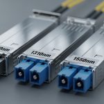
| Wavelength | Typically 850 nm (SR) or 1310 nm (LR) depending on class | 850 nm (SR) or 1310/1550 nm (LR/ER/ZR variants) | Wavelength match to fiber type and plant attenuation budget |
| Connector | LC duplex is common for pluggables; sometimes MTP/MPO on higher density systems | LC duplex common; MTP/MPO often for 40G/100G fanout | Connector type and whether your patch panel uses the same polarity orientation |
| Reach (typical) | SR often designed for tens to a few hundred meters over OM4/OM5; LR farther | SR often tens to ~300 m; LR often up to 10 km depending on optics class | Check OM4 vs OM5, and verify the vendor’s stated reach under a defined link budget |
| Optical budget | SR budget depends on transmitter power and receiver sensitivity for that platform | Similar idea, but the FEC and receiver requirements can differ | Receiver sensitivity and whether your switch applies the same optical power assumptions |
| Management interface | Often compliant with standard pluggable monitoring (commonly I2C with vendor extensions) | MSA-based EEPROM monitoring; some platforms use additional vendor-specific fields | DOM support and whether the switch/HCA reads required fields cleanly |
| DOM data | Tx bias, Tx power, Rx power, temperature, and alarm thresholds | Same general set, but alarm thresholds and calibration can differ | Whether alarms trigger link down or just log events |
| Temperature range | Commercial (0 to 70 C) or extended (-5 to 85 C) depending on module grade | Similar grades by vendor | Whether your rack airflow meets the module’s spec under worst-case load |
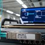
As concrete examples, you might see Ethernet SR optics such as Cisco SFP-10G-SR variants or third-party FS.com SFP-10GSR-85, and InfiniBand optics from switch and HCA vendors that target the InfiniBand electrical expectations. On the optical side, third-party vendors often publish compatible optics part numbers for specific platforms, such as Finisar models like FTLX8571D3BCL for certain Ethernet deployments. Always treat these as reference points, not proof of cross-compatibility.
For standards framing, pluggable modules are commonly aligned with MSA concepts and then tuned by vendors for platform compliance. For Ethernet PHY compliance, IEEE 802.3 remains the reference for optical link behavior. [Source: IEEE 802.3] [Source: SFP and QSFP MSA documentation from vendor consortia]

Compatibility reality: same fiber, different training and lane expectations
In theory, “850 nm SR” sounds interchangeable. In practice, InfiniBand and Ethernet platforms may differ in how they map lanes, enable FEC, and interpret optical diagnostics. Many InfiniBand links are engineered around a specific number of lanes per port and may use proprietary electrical framing. If you drop an Ethernet-optimized optics into an InfiniBand port, the receiver might detect light but still fail link bring-up due to training sequence mismatches or lane ordering assumptions.
Another frequent issue is that Ethernet transceivers may rely on auto-negotiation or specific host configuration steps that InfiniBand does not perform. Conversely, InfiniBand optics can present management data fields that Ethernet switches either ignore or treat as invalid, leading to port disable or conservative fallback modes. Field engineers often observe this as a port that “goes up” but then saturates with CRC-like errors and link flaps under load.
What to check before you swap modules
- Platform optics compatibility list: confirm the exact transceiver part number supported by the HCA or switch.
- Data rate mode: ensure the optics supports the same port speed and lane configuration used by the platform.
- FEC and coding expectations: verify whether the platform enables FEC for that port mode; mismatches can create high error rates.
- DOM thresholds and alarm behavior: confirm the platform’s response to out-of-range Tx bias or Rx power readings.
- Connector polarity and patching: a polarity reversal can look like “bad optics,” but the root cause is often patch panel wiring.
Pro Tip: If a port repeatedly fails training only when the optics are cold (after boot) or only after sustained load, check DOM temperature and optical power drift. Many “bad module” cases are actually airflow/thermal margins or a marginal fiber plant causing Rx power to fall below the threshold during steady-state operation.

Decision checklist: choosing the right transceiver for the fabric
When you are selecting an InfiniBand optical transceiver or an Ethernet alternative, engineers should follow an ordered process that minimizes rework. The goal is to validate not just optical specs, but electrical interface expectations, management compatibility, and operational margins.
- Distance and link budget: measure fiber attenuation at the wavelength you will use; include patch cords, splitters, and connector losses.
- Data rate and port mode: confirm the exact port speed (for example, 56G vs 100G) and lane mapping; avoid assuming “same class equals same mode.”
- Switch or HCA compatibility: use the vendor’s optics matrix for your exact model number; do not rely on generic “SR is SR.”
- DOM support and monitoring fields: verify that the platform reads required DOM parameters and that alarms won’t hard-disable the port.
- Operating temperature and airflow: validate module grade (commercial vs extended) against rack airflow; plan for worst-case summer inlet temperatures.
- Vendor lock-in risk: quantify the cost and lead time differences between OEM optics and third-party equivalents; ensure you can source replacements during outages.
- Maintenance and failure rates: track RMA rates and historical optics failures; include spares planning for your MTTR targets.
Real deployments often mix optics types across tiers. For example, a data center might use InfiniBand optics between compute nodes and a storage tier, while Ethernet optics connect management networks and external gateways. Even if the physical fiber plant is shared, the optics at each endpoint must match the endpoint’s expectations.
Common mistakes and troubleshooting that saves hours
Below are concrete failure modes that frequently appear when teams compare InfiniBand optical transceivers to Ethernet optics and assume interchangeability. Each includes a root cause and a practical fix.
Port never comes up: training mismatch or unsupported port mode
Symptoms: Link stays down, or the switch/HCA logs training failures immediately after insertion. Sometimes the module LEDs look normal, but the port remains inactive.
Root cause: The optics supports the wavelength and nominal rate, but the platform expects a different electrical interface configuration, lane ordering, or link initialization behavior.
Solution: Confirm the exact transceiver part number in the platform’s supported list and reconfigure the port speed mode to match the optics. If you are using third-party optics, validate that the vendor explicitly lists your platform model.
Link flaps under load: marginal optical power or thermal drift
Symptoms: The link comes up, but after sustained traffic you see error counters rise, then link resets or flaps. This can correlate with high rack temperatures.
Root cause: Rx power drops below the receiver sensitivity threshold due to fiber attenuation drift, dirty connectors, or thermal conditions pushing the module out of its optimal operating point.
Solution: Clean connectors using appropriate fiber cleaning tools, re-check patch panel polarity, and compare DOM-reported Tx power and Rx power against vendor thresholds. Improve airflow, and validate the module grade against the rack’s inlet temperature.
Works on one side only: patching polarity or connector mismatch
Symptoms: One direction appears functional briefly, then errors dominate; or the link never establishes even though the optical power readings seem plausible.
Root cause: LC duplex polarity reversal or MPO polarity mismatch. With duplex optics, swapping transmit and receive fibers can create “light present but wrong direction” behavior.
Solution: Verify polarity end-to-end using a known-good test method. Re-terminate or re-patch to match the polarity standard your cabling system uses (for MPO, confirm the specific polarity scheme used in the harness design).
Mismatched FEC expectations: high error rates with stable optical power
Symptoms: DOM looks healthy and link is up, but error counters climb rapidly and throughput is lower than expected.
Root cause: The platform enables (or expects) a particular FEC mode for that port, while the optics or transceiver configuration does not align.
Solution: Check switch/HCA configuration for FEC mode and coding settings for that port speed. Use the vendor’s recommended transceiver configuration profile.

Deployment scenario: where the difference shows up fastest
Consider a 3-tier data center leaf-spine fabric where compute nodes use an InfiniBand fabric for east-west traffic and Ethernet for management and north-south connectivity. You deploy 48-port top-of-rack switches and 192-port spine switches, each with 100G uplinks. In one rollout, the team standardizes on 850 nm SR optics to simplify inventory, but they accidentally install an Ethernet 100G SR module into an InfiniBand uplink port that expects a specific lane mapping and training behavior. The link light may appear, yet the port repeatedly fails to transition to the operational state, causing the HCA to fall back to a slower mode or remain isolated.
Engineers resolved it by replacing the optics with the exact InfiniBand-supported part numbers for that switch and enabling the correct port speed mode. During validation, they measured Rx power at the receiver and confirmed it stayed within the vendor’s minimum sensitivity under worst-case patch cord losses, with rack inlet temperatures held near 28 C. This avoided recurring link resets and reduced troubleshooting time dramatically because the root cause was compatibility, not fiber attenuation.
Cost and ROI: OEM vs third-party optics in production
Pricing varies widely by data rate, reach, and vendor, but engineers typically see OEM optics costing more upfront while third-party optics reduce purchase price. In many environments, an OEM 100G SR optics might run several hundred to over a thousand in local currency-equivalent, while third-party options can be meaningfully lower; however, the real ROI depends on RMA rates, lead times, and whether the optics require special firmware allowances or strict compatibility checks.
Total cost of ownership (TCO) includes labor for rework, downtime during replacement, and the operational risk of inconsistent behavior across batches. If your platform enforces strict transceiver validation, an unsupported third-party optics swap can cost more than the initial savings due to extended troubleshooting and potential port disable events. A practical approach is to pilot third-party optics in a lab or on a low-risk maintenance window, then track error counters and DOM alarms for several weeks before scaling.
For authority and compliance considerations, rely on vendor datasheets and platform documentation rather than marketing claims. [Source: Vendor transceiver datasheets for DOM and compliance]
FAQ
Can I use an Ethernet optical transceiver in an InfiniBand port?
Sometimes, but it is not safe to assume compatibility. Even if wavelength and data rate match, InfiniBand ports may require specific electrical training, lane mapping, or coding/FEC behavior. Always verify against the exact HCA or switch optics compatibility list.
What is the most common reason links stay down after inserting a “compatible-looking” module?
The most common root cause is not light level; it is link bring-up compatibility, including lane mapping and initialization behavior. A second frequent cause is polarity or connector mismatch, especially with duplex or MPO patching.
How do I confirm whether the optics are the problem versus the fiber plant?
Use DOM to check Tx power and Rx power, then validate with an optical power meter and a fiber inspection scope. If Rx power is healthy and errors persist, suspect FEC/coding expectations or training mode mismatches; if Rx power is low, suspect attenuation, dirty connectors, or bad patching.
Do DOM alarms behave the same across vendors?
No. DOM thresholds and how the platform reacts to alarms can differ. Some platforms log warnings and continue, while others disable the port when parameters cross strict limits.
Are OM4 and OM5 interchangeable for these optics?
Often they are compatible for 850 nm SR, but reach margins can change because OM5 is optimized for wider wavelength ranges. Use the vendor’s stated reach for your exact fiber type and include patch cord losses in the link budget.
What should I standardize to reduce future outages?
Standardize on optics that are explicitly supported by your platform and keep a small tested spare kit for each optics class. Also standardize patching polarity and document the exact transceiver part numbers used per rack and tier.
If you want a next step, review how port speed modes and FEC settings affect optical bring-up, then align your transceiver selection accordingly via Ethernet vs InfiniBand link behavior. With that, you can reduce “it should work” assumptions and build a repeatable optics strategy for upgrades.
Author bio: I have deployed and debugged high-speed fiber links in production data centers, focusing on optics compatibility, DOM monitoring, and failure analysis. I write practical network engineering guidance grounded in vendor documentation and observed field behavior.