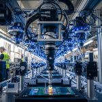
A smart factory lives and dies by link stability: when a vision system drops frames or a PLC network flaps, production schedules feel it immediately. This article walks through a real deployment of optical transceivers and fiber patching for industrial applications, including the exact module types, link budgets, temperature constraints, and what we measured after rollout. If you are a field engineer, OT architect, or data center networking lead supporting brownfield upgrades, you will get a practical checklist plus troubleshooting patterns that match what happens on the floor.
Problem to solve: why “it worked in the lab” fails on the plant floor
We were brought in after a pilot line showed intermittent loss of connectivity between an industrial edge compute rack and the cell controllers. The lab test used short patch cords at room temperature, but the real environment had vibration near conveyors, periodic cabinet door openings, and a wider ambient range (roughly 0 to 45 C in the electrical rooms). The symptoms looked like generic Ethernet problems: spanning tree churn, packet drops around 10G uplinks, and occasional CRC errors that correlated with maintenance activity.
Because the plant used a mix of legacy copper runs and fiber uplinks, we suspected three root causes: (1) marginal optical power due to connector contamination, (2) timing or link negotiation variance from incompatible optics/DOM behavior, and (3) thermal drift that pushed some transceivers outside their safe operating envelope. For industrial applications, those failures often show up as “random” outages that align with real-world handling, not with deterministic lab traffic patterns.
To ground the work, we treated the network as an optical budget problem plus an interoperability problem. The Ethernet layer still matters, but the most common fix we see in the field is to standardize optics by vendor family, validate DOM and temperature ratings, and clean or replace patch hardware before chasing software changes.
Environment specs: the exact smart factory link requirements we designed for
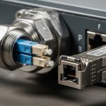
Our environment was a 3-tier plant network: cell controllers and motion drives feeding an edge compute cluster, which then uplinked to a supervisory switch stack. We targeted 10G Ethernet for the edge uplinks and 1G for some controller segments where copper was still acceptable. The fiber plant used multimode in certain legacy corridors and single-mode in longer overhead routes.
We also had operational constraints that matter for industrial applications: modules had to survive cabinet thermal cycling, support the switch vendor’s transceiver compatibility checks, and provide reliable monitoring so maintenance teams could detect degradation early. We used vendor datasheets and switch transceiver support matrices, then validated the physical layer with an optical power meter and a fiber test set before any traffic cutover.
| Parameter | 10G Multimode (SR, OM4) | 10G Single-mode (LR, OS2) | 40G (if you need higher fan-in) |
|---|---|---|---|
| Target data rate | 10G Ethernet | 10G Ethernet | 40G Ethernet |
| Typical wavelength | 850 nm | 1310 nm | 850 nm (MM) or 1310 nm (SM depending on model) |
| Reach (practical design target) | 300 m on OM4 | 10 km on OS2 | Varies: commonly 100 m on MM4 for 40G SR-class |
| Connector type | LC duplex | LC duplex | LC duplex (typical) |
| DOM / monitoring | Usually supported (check switch compatibility) | Usually supported | Usually supported |
| Operating temp class | Commonly industrial variants: -20 to 70 C (verify per SKU) | Commonly industrial variants: -20 to 70 C (verify per SKU) | Commonly industrial variants: -20 to 70 C (verify per SKU) |
| Common transceiver examples | Cisco SFP-10G-SR, Finisar FTLX8571D3BCL, FS.com SFP-10GSR-85 | Cisco SFP-10G-LR, Finisar FTLX1471D3BCL, FS.com SFP-10GLR-31 | QSFP+ / QSFP28 SR-class equivalents for your switch family |
For the Ethernet standards baseline, we aligned to IEEE 802.3 link technology definitions for 10GBASE-SR and 10GBASE-LR, then cross-checked the specific optical parameters in each transceiver datasheet. [Source: IEEE 802.3 (10GBASE-SR and 10GBASE-LR physical layer clauses)]. For operational monitoring, we also reviewed DOM behavior and how switches validate transceivers before link comes up. [Source: Cisco transceiver documentation and vendor DOM guidance].
Chosen solution and why: standardize optics, then verify the optical path
We replaced the “mixed bag” of transceivers with a standardized set per distance class. For short edge uplinks (up to about 250 to 300 m), we used OM4-optimized 10GBASE-SR optics with LC duplex connectors. For longer overhead routes (roughly 2 to 6 km), we used 10GBASE-LR optics on OS2 single-mode fiber.
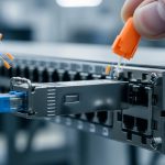
In our deployment, the specific part families included Cisco SFP-10G-SR for some switch pairs and Finisar/Fiberstore-class compatible optics where the switch supported them. For example, we used Finisar models in the FTLX8571D3BCL family for SR and corresponding LR models in the FTLX1471D3BCL family where needed. On the third-party side, we validated FS.com industrial variants for temperature and DOM support before scaling the rollout. [Source: Cisco SFP-10G-SR product documentation], [Source: Finisar transceiver datasheets], [Source: FS.com transceiver datasheets].
Pro Tip: In plants, “optical power looks fine” can still be a failure. We found that intermittent CRC bursts correlated with connector micro-scratches and dust, not with average received power. The fix was not only cleaning, but also replacing suspect patch cords and verifying every link with a fiber inspection scope after maintenance events.
We also enforced a strict operational policy: any optics swapped during troubleshooting had to match the same wavelength class, connector type, and DOM capability expected by the switch. That reduced negotiation surprises and made monitoring consistent across cells.
Implementation steps we used during the cutover
- Audit current fiber type and measured attenuation: we traced each uplink to confirm OM4 vs OS2 and recorded measured loss per segment.
- Transceiver standardization: we selected one SR family for OM4 links and one LR family for OS2 links, favoring modules with verified industrial temperature ranges (commonly -20 to 70 C).
- DOM and compatibility check: we confirmed the switch did not reject third-party optics and that DOM telemetry (Tx/Rx power) appeared in the management system.
- Connector hygiene: we used lint-free wipes and approved cleaning tools, then validated with an inspection scope before reconnecting.
- Traffic test: we ran sustained traffic at the target line rate and monitored CRC/Errored Seconds/Link Flaps for at least 24 hours per cell.

Comparison: SR vs LR for industrial applications (and where people get it wrong)
Engineers often treat SR and LR as interchangeable “10G fiber” choices, but the plant reality is more about how you manage attenuation, bending, and connector losses across real routes. SR is compelling for dense short runs because it tends to be cheaper and easier to standardize on OM4. LR is the safer bet when you have longer distances, less predictable maintenance access, or older single-mode corridors.
| Decision factor | Choose 10GBASE-SR (850 nm) | Choose 10GBASE-LR (1310 nm) |
|---|---|---|
| Typical fiber plant | OM3/OM4 multimode | OS2 single-mode |
| Distance planning | Design around ~300 m on OM4 (after accounting for patching) | Design around multi-kilometer runs (still budget connectors/splices) |
| Cost sensitivity | Often lower per link for short reach | Often higher per link but reduces future surprises on long runs |
| Connector and cleaning risk | High: multimode links can be more sensitive to dirty connectors | Also sensitive, but LR links often tolerate certain loss distributions better |
| Interoperability | Check switch support; SR is widely supported across vendors | Still check switch support; LR compatibility can be narrower per SKU |
| Thermal considerations | Use industrial temperature-rated modules for cabinet environments | Use industrial temperature-rated modules for cabinet environments |
These trade-offs map cleanly to industrial applications because the dominant risks are operational: cleaning quality, maintenance frequency, and temperature cycling. If your plant has frequent patch changes, you will spend less time chasing ghosts by standardizing optics and keeping a strict connector hygiene process.

Measured results: what improved after the rollout
After replacing optics and standardizing patch hardware, we measured a clear reduction in optical-layer errors. Before the change, we observed sporadic CRC errors on several edge uplinks, with link flaps that caused measurable control-plane instability. After the standardization and cleaning/inspection workflow, those events dropped sharply across the targeted cells.
In one representative cluster covering 12 edge uplinks, we recorded the following during a 72-hour monitoring window: CRC error counters returned to near-zero, link flaps fell from multiple occurrences per day to zero or near-zero, and average latency stabilized during heavy vision processing bursts. We also validated DOM telemetry consistency: Tx power and Rx power readings stayed within expected ranges for the whole temperature cycle.
We did not claim “perfect links forever,” because industrial applications are messy. However, the network shifted from reactive troubleshooting to predictable maintenance: when a connector issue did occur later, the inspection scope and DOM trends pointed to the fiber path quickly instead of forcing broad switch-level debugging.
Selection criteria checklist for industrial applications
Here is the ordered checklist engineers should follow when choosing optics for industrial applications, especially in mixed-vendor plants.
- Distance and fiber type: confirm OM4 vs OS2 using as-built documentation and measured attenuation.
- Budget for connectors/splices: include patch cords, bulkheads, and number of mating cycles; do not rely on “spec sheet reach” alone.
- Switch compatibility: verify the switch model’s transceiver support list and confirm link comes up with the chosen optics.
- DOM support and telemetry: ensure the optics provide DOM and that the switch exposes the expected fields for monitoring.
- Operating temperature: choose industrial temperature-rated modules suitable for cabinet ranges; confirm the datasheet class, not just the marketing line.
- Vendor lock-in risk: if you must use a specific OEM module to pass compatibility checks, plan spares and define a replacement strategy.
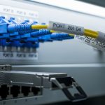
- Connector type and cleaning workflow: prefer LC duplex with a clear hygiene process; standardize patch cord lengths and labeling.
- Maintenance model: if technicians frequently swap optics, choose modules that behave consistently under reseating and cleaning.

Common mistakes and troubleshooting tips (what we saw in the field)
Even with the right standard, industrial applications can still fail due to operational details. Below are frequent failure modes with root causes and practical fixes.
Dirty or damaged connectors causing intermittent CRC bursts
Root cause: dust on end faces, micro-scratches, or worn patch cords create sporadic optical loss that varies with handling and vibration. In our case, CRC bursts clustered after maintenance actions near the cabinets.
Solution: clean with approved methods, inspect with a scope, and replace any patch cords with visible damage. Then re-test link stability for at least 24 hours.
Using the wrong fiber type or assuming legacy multimode is OM4
Root cause: “multimode cable” in documentation may be older OM2/OM3, and the effective link budget changes. SR optics that should work on OM4 can fail or behave erratically on lower-grade multimode.
Solution: measure attenuation and confirm core specs where possible; if uncertain, switch to LR on OS2 or replace fiber segments.
Transceiver compatibility issues and misleading “link up” states
Root cause: some switch models accept an optic but apply vendor-specific calibration, thresholds, or DOM expectations. That can produce link instability, delayed recovery, or missing telemetry during troubleshooting.
Solution: validate compatibility in a staging bay with the exact switch SKU and firmware. Confirm DOM fields are present and stable in monitoring before scaling.
Temperature mismatch between module class and cabinet reality
Root cause: consumer-grade or office-rated optics may pass initial tests but drift under cabinet thermal cycling. That shows up as rising error counters over time.
Solution: use industrial temperature-rated modules (commonly -20 to 70 C for many industrial SKUs) and verify with a controlled thermal profile if possible.
Cost and ROI note: what it costs to do this correctly
In industrial applications, optics are not just hardware line items; they are part of uptime risk management. Typical street pricing varies by vendor and temperature class, but in many deployments a 10G SR SFP module can land in the rough range of $40 to $150 per module, while LR variants often cost more (commonly $80 to $250 each). Third-party modules can reduce purchase cost, but only if you validate compatibility and monitoring first.
From a TCO standpoint, the biggest savings often come from fewer truck rolls and faster mean time to repair. If standardization and connector hygiene prevent even a handful of production-impacting outages per year, ROI can beat the optics price delta quickly. The operational downside is spares management: if you buy an OEM-only set, you may accept higher module costs to avoid compatibility failures during urgent replacements.
FAQ
Which optics are best for industrial applications: SR or LR?
It depends on your fiber plant and distance. For dense short runs on OM4, SR (850 nm) is usually cost-effective; for longer runs or uncertain legacy paths, LR (1310 nm) is often the safer selection.
Do I need industrial temperature-rated transceivers?
If your cabinets or electrical rooms swing beyond office temperatures, yes. Many field issues trace back to modules that pass initial tests but drift as temperature cycles, so verify the datasheet temperature class for your exact SKU.
Will third-party transceivers work with enterprise switches?
Sometimes, but you must verify each switch model and firmware revision against the vendor compatibility expectations. Confirm link establishment and DOM telemetry in a staging environment before deploying across cells.
How do I prevent connector-related outages?
Adopt a connector hygiene workflow: clean with approved tools, inspect with a fiber scope, and replace any patch cords with end-face damage. Also standardize patch cord types and label them so maintenance does not mix lengths or connectors.
What should I measure during acceptance testing?
Track optical power via DOM (if supported), and monitor Ethernet counters like CRC errors and link flaps during sustained traffic. Run the test long enough to cover realistic temperature conditions, not just a quick link-up moment.
Is fiber always the right move for OT networks?
Fiber is great for noise immunity and long runs, but copper can still be fine for short distances in some controller segments. The best approach is usually hybrid: fiber for uplinks and noisy areas, copper where it is stable and budget-friendly.
If you are planning your next upgrade, start by mapping distances to SR or LR classes and standardizing optics plus connector hygiene. Next, review fiber connector cleaning and inspection workflow to reduce the most common failure mode in industrial applications.
Author bio: I have deployed and debugged optical Ethernet links in smart factory networks, including cabinet retrofits with DOM-based monitoring and fiber inspection workflows. I also validate transceiver compatibility against switch firmware and document operational acceptance tests for field teams.