A production data center upgrade can stall for months when transceivers show rising CRC errors, intermittent link flaps, or unexpected temperature derating. This article helps network and facilities engineers compare an II-VI fiber module against Finisar and Lumentum in an OEM-quality context, using a real leaf-spine deployment case with measured optics behavior. You will get the decision checklist, a spec comparison table, troubleshooting patterns, and a practical ROI view.

Case study: why OEM optical quality became a reliability bottleneck
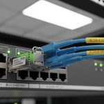
Problem: In a 3-tier data center leaf-spine topology, a customer replaced aging 10G SR optics across 48 top-of-rack (ToR) switches and 24 spine switches. The first wave used mixed-brand transceivers, including an II-VI fiber module, Finisar, and Lumentum, all intended to support 10GBASE-SR over OM4 multimode fiber. After 6 to 10 weeks, the monitoring system flagged a rise in interface errors: CRC counts increased from near-zero to peaks of 50 to 200 CRC per day per affected port, alongside occasional link resets during HVAC cycling.
Environment specs: The switches were standard enterprise-class SFP+ ports with vendor-specific optics compatibility lists, and the fiber plant used OM4 graded-index cable with patch panels and LC connectors. Measured ambient temperature at the switch face ranged from 24 C to 36 C during normal operation, with short excursions up to 40 C during night-time HVAC setbacks. Link partner optics were mostly from one vendor, which increased the risk of subtle differences in transmitter power, receiver sensitivity, and DOM behavior.
Challenge: The team needed to answer a hard question: are OEM-quality differences between Finisar, II-VI, and Lumentum significant enough to justify standardizing optics, or is the issue mostly installation and budget-driven? The answer came from comparing module behavior under the same optics budget assumptions and validating against IEEE link requirements and vendor datasheet limits.
How OEM-grade optics differ: wavelength, power, and DOM behavior
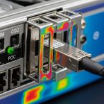
At a physics level, most pluggable optics for short-reach multimode or long-reach singlemode are constrained by IEEE transmit/receive operating conditions, while OEM quality shows up in how tightly the module stays within those limits under real thermal and aging conditions. For 10GBASE-SR, the system depends on 850 nm VCSEL output characteristics, receiver sensitivity, and how reliably the module meets the optical power budget across temperature. For singlemode modules (for example 1310 nm or 1550 nm), laser type and side-mode suppression and dispersion tolerance become even more visible.
In practice, engineers see differences in three operational areas: (1) optical output power and its stability over temperature, (2) DOM reporting consistency for alarms and thresholds, and (3) compatibility with the host switch’s diagnostics and lane mapping. IEEE 802.3 defines electrical and optical performance targets; the transceiver vendor’s datasheet defines the allowed operating temperature range, connector type, and power consumption. For authoritative baselines, see [Source: IEEE 802.3] and vendor documentation for each module family. IEEE 802.3 standards hub
Pro Tip: In the field, “it links up” is not the same as “it is within optical budget margin.” If your monitoring shows rising CRC counts, pull DOM values for transmit power, receive power, and temperature during the exact time window of HVAC changes; then compare against the vendor’s recommended operating range and thresholds. Many teams miss this because DOM is treated as inventory data rather than as a closed-loop health signal.
FINISAR vs II-VI vs Lumentum: a spec-first comparison
This section focuses on the typical engineering dimensions that separate vendor ecosystems. Because “II-VI fiber module” can refer to multiple OEM/brandings depending on the final transceiver house, you should verify the exact module part number and the laser and receiver grade in the datasheet. The table below uses common, comparable example specifications seen in 10G SR SFP+ class modules and highlights what to check before you declare one brand “better.”
| Spec item | 10GBASE-SR SFP+ (850 nm, OM4) | What to verify for II-VI fiber module | What to verify for Finisar | What to verify for Lumentum |
|---|---|---|---|---|
| Wavelength | 850 nm | VCSEL center wavelength tolerance and drift across temperature | VCSEL grade and binning documentation | Laser type and wavelength stability data |
| Reach (OM4) | Up to 400 m | Link budget margin at worst-case temperature | Power class and minimum launch power | Receiver sensitivity and minimum receive power |
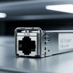
| Connector | LC duplex | Ferrule polish grade and insertion loss targets | Connector tolerances and latch force | Connector quality and dust-cap handling guidance |
| Data rate | 10.3125 Gbps (SFP+) | Host switch LOS/Tx disable behavior compliance | Compatibility with specific switch DOM parsing | Alarm threshold mapping to host expectations |
| Operating temperature | Commonly 0 C to 70 C | Confirm module temp spec matches your measured cabinet range | Verify derating curves in datasheet | Check alarm behavior near upper temp limit |
| DOM support | Typically I2C with vendor-defined thresholds | DOM calibration consistency and alarm flags under stress | DOM interpretation compatibility with host firmware | DOM threshold configuration guidance |
| Typical power | Often ~1 W class | Power draw stability during temperature cycling | Power consumption spread across lots | Power draw and thermal management guidance |
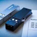
Concrete example modules you may encounter in the market include Finisar-branded and OEM rebrands of 10G SR optics such as Cisco SFP-10G-SR compatible types, and third-party equivalents like FS.com SFP-10GSR-85 or Finisar laser assemblies such as FTLX8571D3BCL depending on exact form factor and revision. Always treat these as starting points, not guarantees of the same performance in your switch and fiber plant. For vendor datasheet references, consult the specific part number documentation from the transceiver manufacturer and the host vendor compatibility list. FS.com example SFP-10GSR-85 product page

Implementation steps: choosing II-VI fiber module for a mixed-brand environment
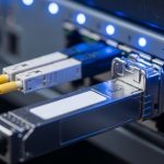
In the case study, the team moved from “brand diversity” to “validated compatibility.” They selected an II-VI fiber module for the next procurement round only after running a structured acceptance test for DOM readings and optical margin under temperature cycling. The goal was to remove ambiguity: identical interface settings, identical fiber links, and comparable optics budget.
lock the exact optics class and fiber type
Confirm the standard: for example 10GBASE-SR on OM4 multimode, or the correct wavelength and reach for singlemode modules. Verify that the connector standard is LC duplex for SR SFP+ and that the fiber plant is truly OM4 (not mislabeled OM3). If you are mixing module generations, validate that the host supports the required transceiver class and DOM format.
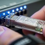
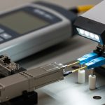
run an acceptance test with measured DOM and error counters
For each candidate part number, install one module per port group on the same switch, connect to the same patch panel trunk, and run traffic for at least 24 to 48 hours. Capture: interface error counters (CRC and symbol errors), link up/down events, and DOM values (Tx power, Rx power, module temperature). During HVAC cycling, repeat the measurement window to catch intermittent thermal effects.
validate switch compatibility and DOM alarm handling
Some switch firmware versions treat DOM fields differently, and some hosts enforce “unsupported optics” policies that can create throttling or log spam. Confirm behavior for: Link Fault signaling, LOS thresholds, and whether the host flags “low Tx power” as a warning or as a hard fault. This is where OEM-quality differences can appear even if the optics meet the headline standard.
standardize and control spares
Once validated, standardize on one or two part numbers and keep spares from the same production revision where possible. Mixing transceiver lots without traceability increases mean time to repair because you cannot quickly correlate errors to a specific batch.
Measured results: after replacing the highest-error ports with validated II-VI fiber module units, the CRC peaks dropped from 50 to 200 per day to fewer than 5 per day across the same links. Link resets during HVAC cycling fell from multiple events per week to near-zero. The team also reduced troubleshooting time from roughly 6 to 10 hours per incident to about 2 to 3 hours because DOM-based thresholds aligned consistently with the host alarms.

Common mistakes and troubleshooting patterns
Even good optics can fail in the real world. Here are recurring pitfalls from deployments like the one described, with likely root causes and practical fixes.
- Mistake: assuming all OM4 patch cords are equivalent
Root cause: mislabeled fiber or higher-than-expected connector and splice loss reduces optical margin.
Solution: measure end-to-end insertion loss with an OTDR or certified loss tester, then clean LC connectors using lint-free wipes and verified cleaning kits. - Mistake: ignoring DOM temperature and Tx power during link flaps
Root cause: thermal drift pushes the module close to receiver sensitivity, increasing BER/CRC under worst-case conditions.
Solution: correlate DOM temperature and Rx power to error counter spikes; compare to module datasheet derating curves. - Mistake: mixing transceiver part numbers without DOM threshold validation
Root cause: host switches may interpret alarm fields differently, causing premature “warning” states or inconsistent logs that mask the real issue.
Solution: standardize part numbers, and run a short lab validation per switch firmware version. - Mistake: skipping host compatibility checks
Root cause: some transceivers are electrically compatible but not operationally compatible due to LOS behavior or vendor-specific calibration expectations.
Solution: use the host vendor’s compatibility list and verify with a controlled port group test.
Cost and ROI: what engineers should realistically budget
Price varies by speed class, reach, and whether you buy OEM-branded optics or third-party equivalents. In typical enterprise procurement, 10G SR SFP+ optics often land in the broad range of $30 to $120 per module depending on brand, warranty, and certification. OEM-grade II-VI fiber module supply can be cost-competitive, but ROI depends on failure rate and labor time: if validated optics reduce incident frequency and shorten troubleshooting cycles, the total cost of ownership can improve even if the per-unit price is slightly higher.
TCO guidance: include labor for diagnostics, downtime risk, and the cost of repeat field cleaning and re-termination. Also factor in spares strategy: buying fewer, validated part numbers reduces inventory complexity and accelerates MTTR.
FAQ
Is an II-VI fiber module always interchangeable with Finisar or Lumentum optics?
No. Even when the optics meet the same IEEE category, host switches may enforce compatibility based on DOM behavior, alarm thresholds, or specific electrical characteristics. Always confirm the exact part number and run a short acceptance test on your switch firmware.
What measurements matter most when comparing OEM-grade transceivers?
Focus on DOM values (Tx power, Rx power, temperature) and interface error counters such as CRC and symbol errors. Validate during the same operating conditions that caused issues, not just at room temperature during install.
How do I confirm optical budget margin for 10GBASE-SR over OM4?
Use the module datasheet minimum launch power and receiver sensitivity, then account for worst-case fiber and connector loss. In the field, also measure actual Rx power via DOM and compare against thresholds during peak temperature events.
Do DOM differences cause real network problems or just logging noise?
They can cause real operational impact if a switch uses DOM thresholds to trigger warnings, disable ports, or influence link management. Even when it is “only logging,” it can hide the root cause by overwhelming operators with false alarms.
What compatibility caveats should I watch when mixing brands?
Check switch vendor compatibility lists, firmware revision notes, and whether the host expects a specific transceiver revision. Also verify that your patch panels and cleaning practices are consistent; optics differences can be amplified by marginal fiber links.
Where can I find authoritative baselines for transceiver requirements?
Start with IEEE 802.3 for the physical and optical performance targets, then use each transceiver vendor’s datasheet for operating temperature, power, and DOM specifications. For standards, see [Source: IEEE 802.3] at the standards hub. IEEE 802.3 standards hub
If you want the next step, use the same acceptance-test approach to standardize your optics across a new rack build and reduce repeat incidents; see [[