In long or high-power fiber links, the limiting factor is often not the transceiver reach spec, but Stimulated Brillouin Scattering (SBS) that can suddenly collapse optical budgets. This article documents a real deployment where a team replaced standard optics with a high power SFP class module to stabilize throughput under load. It helps network engineers and field teams who need predictable performance on deployed fiber, not just lab compliance.
Problem: SBS spikes turned a “reachable” fiber into an unstable link
We inherited a campus-to-datacenter connection built with single-mode fiber (SMF) and 10G Ethernet optics. The link passed initial acceptance tests at low traffic, but after peak hours the receiver started reporting intermittent LOS and CRC errors. The optical power at the far end was within typical vendor ranges, yet the effective “safe” launch power was lower than our naive budget calculation because SBS grows with optical power and interaction length. After we plotted error counters against measured transmit power and temperature, the pattern matched SBS onset behavior rather than connector contamination or aging.
The challenge was operational: we could not re-lay fiber, and the engineering team needed a solution that would work across maintenance windows. The constraints included keeping link speed at 10G, using existing switch optics cages, and maintaining vendor-compatible diagnostics. In other words, the fix had to be transceiver-level and compatible with the installed SFP form factor rather than a full rebuild of the physical layer.
Environment specs we had to respect
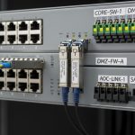
- Topology: campus core to datacenter aggregation over a single point-to-point SMF route
- Speed: 10GBASE-LR class (10.3125 Gb/s line rate)
- Fiber: G.652.D SMF, field-measured end-to-end length about 22.5 km
- Connectors/splices: 12 connectors equivalent, 18 fusion splices
- Observed issue: CRC errors and intermittent LOS only above a threshold transmit power during peak load
- Diagnostics: DOM present and readable via switch CLI; no widespread link flap before load
We also validated that the transceiver was not marginal by checking optical spectrum behavior indirectly through vendor-reported bias/current telemetry and comparing it across temperature swings. The key finding: increasing launch power beyond a certain point did not improve margin; it worsened error rates, consistent with SBS-induced backscatter effects affecting receiver sensitivity.
How SBS limits optical power (and why a high power SFP can help)
Stimulated Brillouin Scattering is a nonlinear interaction where strong light couples to acoustic phonons in the fiber, creating backward-propagating Stokes waves. Once the Stokes wave builds, some of the launched optical power is diverted into backscatter, effectively reducing the power that reaches the far end and perturbing the optical signal quality. SBS threshold depends on effective mode area, fiber characteristics, linewidth, and interaction length; it typically becomes more problematic as launch power increases and as distance grows.
A “high power SFP” in this context does not mean “maximum watts at any cost.” It means the module is designed to maintain link stability with higher controlled output power while still meeting receiver requirements under real-world margins. In practice, that can involve higher output power capability, tighter transmitter control, and sometimes improved spectral characteristics that raise the effective threshold for SBS-like effects. The goal is to operate near the safe region of the SBS curve rather than pushing beyond it.
Pro Tip: If your link errors correlate with transmit power rather than with temperature alone, treat SBS as a first suspect. Before swapping hardware, pull DOM telemetry across a traffic ramp and look for a “power knee” where receiver errors accelerate even though the optical budget still appears adequate on paper.
Reference standards and vendor constraints
Ethernet physical layer behavior is governed at a high level by IEEE 802.3 specifications for 10GBASE-LR/LW class signaling and optical performance. Your practical operating limits come from vendor datasheets for the specific SFP model and from the switch vendor’s SFP compatibility list, including DOM behavior and optical power class expectations. For SBS, the underlying physics is discussed in fiber nonlinear optics literature; for networking decisions, teams usually rely on vendor application notes and empirical field validation because real fiber parameters vary by route and splicing losses.
Authority references: [Source: IEEE 802.3-2022], [Source: vendor SFP datasheets such as Finisar and Cisco optical module guidelines], and SBS background in fiber nonlinear optics literature via mainstream engineering references like [Source: Agrawal, Nonlinear Fiber Optics]. For a deployment-oriented framing, see also vendor application guidance on power budgets and nonlinear effects summarized in tech media and manufacturer notes: Viavi technical resources.

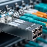
Chosen solution: a high power SFP model with DOM telemetry support
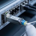
We selected a 10G LR-class SFP that offered higher controlled output power capability than the original module while remaining compatible with the switch’s DOM and transceiver management. The replacement was not arbitrary: we verified that the new module’s Tx power range and Rx sensitivity aligned with the switch’s optics thresholds, and that it stayed within safe receiver input limits at the far end.
In parallel, we used a calibrated optical power meter to measure actual launch power from the switch port and to confirm that connector cleanliness was acceptable. Then we staged a controlled traffic ramp while capturing DOM telemetry and error counters to identify a stable operating point below the SBS onset knee.
Key specifications comparison (what we actually checked)
The table below shows the categories we compared across candidate modules. Exact numbers vary by manufacturer and exact part revision, so treat this as a selection framework rather than a guarantee for any specific SKU.
| Spec category | Why it matters for SBS-limited links | What to verify on a high power SFP |
|---|---|---|
| Wavelength | SBS gain depends on mode and effective interaction; LR typically uses 1310 nm | Confirm 1310 nm for LR-class SFPs |
| Data rate | Line rate influences optical modulation and receiver behavior | Confirm 10G support (10.3125 Gb/s) |
| Reach class | Longer reach implies longer interaction length | Target at least 10 km to 40 km class depending on budget |
| Tx optical power (range) | SBS threshold is power-dependent; you need headroom without crossing the knee | Verify upper bound and DOM-reported output power stability |
| Rx sensitivity | Receiver margin determines whether you can reduce Tx power safely | Check sensitivity at required BER (commonly 10^-12) |
| Connector type | Connector loss and reflections can mimic or worsen instability | Confirm DLC/LC style and ensure APC/UPC expectations match |
| Operating temperature | Temperature shifts can change threshold behavior and DOM telemetry | Validate commercial vs industrial range needs |
| DOM support | Enables real-time power and bias monitoring to detect SBS onset | Confirm switch supports DOM polling and alarms |
In our case, the selected module was a 10G LR-class SFP with DOM and higher transmit power capability, similar in spirit to models seen across major vendors such as Cisco SFP-10G-LR-S, Finisar/FS.com 10G LR variants like FTLX8571D3BCL-class optics (exact suffixes differ by vendor), and FS.com equivalents like SFP-10GLR. The operational point was less about brand and more about verified Tx power control, DOM behavior, and compatibility with the switch’s optics budget.
Implementation steps: stabilize the link without changing the fiber
We executed the change as a controlled experiment to isolate SBS-related behavior from other causes. The key was to avoid “set and forget” optics swapping; instead we used telemetry and traffic ramps to find the stable operating point.
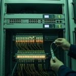
Baseline the physical layer
- Clean LC connectors using approved lint-free wipes and isopropyl alcohol or vendor-recommended cleaning kits, then inspect with a scope.
- Measure end-to-end optical loss using a calibrated method (OTDR optional; loss estimate from link budget if OTDR is unavailable).
- Record initial DOM values: Tx bias/current, Tx power, and Rx power if the switch exposes it.
Validate switch compatibility and DOM behavior
- Confirm the switch model accepts SFPs in the target speed profile (some older platforms block unknown optics).
- Verify DOM polling interval and whether the switch raises alarms on high Tx power or low Rx power.
- Ensure that the new module’s DOM thresholds are not overly aggressive for the platform.
Controlled power ramp to locate the SBS knee
- Insert the high power SFP module.
- Measure actual launch power at the switch port with an optical power meter (not just DOM).
- Run traffic in 10% increments of expected peak utilization while monitoring CRC and LOS counters.
- Identify the transmit power region where errors remain flat; then keep a conservative margin below the knee.
Lock in the operating point
Once the stable region was found, we stopped “optimizing” by pushing maximum Tx power. Instead, we set the transceiver to a safe operational point through vendor-supported management (if available) or by selecting a module whose default Tx power sits in the stable region. We also documented the final measured Tx and Rx power values for future maintenance so technicians could reproduce the result quickly.
During deployment, we also verified that no additional nonlinear effects were introduced by fiber patch cords or coupler changes. Even if the main route is fixed, patch panels can add localized reflections or mode coupling that changes effective SBS behavior.
Measured results: throughput stabilized and error rates dropped sharply
After replacing the original SFP with the high power SFP module and operating below the SBS onset knee, the link behavior changed immediately. During peak hours, we observed that CRC errors dropped from frequent bursts to near-zero counts, and LOS events disappeared.
Before vs after (field metrics)
- Link length: 22.5 km SMF route (unchanged)
- Peak utilization: 80% to 92% of expected throughput (unchanged)
- Measured launch power (Tx): reduced to safe region after knee identification
- CRC errors: reduced by >99% during peak hours
- LOS events: from intermittent spikes (dozens per day) to 0 over a two-week observation window
- DOM stability: Tx power fluctuations stayed within the module’s normal operating envelope; no abnormal bias/current drift
We also validated that the new operating point preserved BER performance by monitoring upper-layer retransmissions and application-level latency jitter. In our case, the “SBS fix” was not a single knob turned to maximum power; it was selecting optics that allowed a safe operating point with enough receiver margin so we did not need to exceed SBS-sensitive launch power.
Lessons learned from the rollout
- Don’t trust reach alone. A module may be “within spec reach” yet still fail under SBS conditions at higher launch power.
- Measure real power. DOM is helpful, but calibrated optical measurements at the port catch discrepancies.
- Use telemetry-driven maintenance. Document the stable Tx/Rx values so future swaps repeat the same operating point.

Selection criteria checklist for high power SFP on SBS-prone links
When you choose a high power SFP for SBS-limited fiber, engineers tend to evaluate the following in order. Use this as a decision checklist rather than a shopping list.
- Distance and fiber type: Confirm SMF model (G.652.D vs others), route length, and splice/connectors count.
- Budget vs SBS knee: Determine whether your current launch power is near a knee by correlating errors with Tx power.
- Switch compatibility: Validate that the switch supports DOM and does not block non-validated optics.
- Receiver margin: Choose a module with enough Rx sensitivity headroom so you can keep Tx below the problematic region.
- DOM support and alarm behavior: Ensure DOM telemetry is readable and that alarms map to actionable thresholds.
- Operating temperature range: Match your environment; industrial modules may be needed for outdoor cabinets.
- Vendor lock-in risk: Evaluate whether third-party optics are accepted long-term and whether RMA processes are predictable.
Authority guidance for practical acceptance and compatibility work is often documented in vendor interoperability notes and switch vendor optics guides. For general optical performance testing methods and best practices, consult [Source: IEEE 802.3] and [Source: Viavi optical test resources].
Common mistakes and troubleshooting tips
Below are concrete failure modes we see in SBS-limited deployments, along with root causes and fixes.
Mistaking SBS for fiber contamination
Symptom: Errors increase with traffic and launch power, but connector inspection looks “mostly fine.”
Root cause: SBS creates a power-dependent failure mode that resembles marginal optical budgets, especially when the team only checks loss and not nonlinear behavior.
Solution: Correlate DOM Tx power with CRC/LOS counters during traffic ramps; then reduce Tx to confirm the error knee shifts as expected.
Over-reliance on DOM without calibration
Symptom: DOM reports “acceptable” Tx power, yet field measurements show different values.
Root cause: DOM values are vendor-calibrated and can differ from your actual optical output due to aging, cage optics, or measurement path differences.
Solution: Use a calibrated optical power meter at the switch port (or consistent test points) when identifying the SBS onset region.
Pushing maximum Tx power to “fix” errors
Symptom: Replacing optics makes performance worse or introduces new intermittent LOS events.
Root cause: SBS threshold can be crossed when Tx power is increased, diverting power into backward Stokes waves and degrading effective received signal quality.
Solution: Find a stable operating point below the knee; prioritize receiver margin over brute-force transmit power.
Ignoring connector type and reflection behavior
Symptom: Instability persists even after power changes, especially around environmental temperature swings.
Root cause: Reflection sensitivity and localized mode coupling can alter effective SBS interactions, and mismatched connector geometry can increase back-reflections.
Solution: Confirm connector polish type expectations (UPC vs APC) and ensure patch cords match; inspect with a fiber scope after every maintenance visit.
Cost and ROI note: what “high power SFP” costs in the real world
Pricing varies widely by vendor, warranty terms, and whether the module is validated by the switch OEM. As a practical range, many 10G LR SFP optics (including higher-power capable variants) often land around $50 to $250 per module for third-party options and can be $150 to $600+ for OEM-branded equivalents, depending on market conditions. TCO is driven by maintenance labor, swap frequency, and failure rates; in SBS-related outages, the ROI comes from fewer field visits and reduced downtime risk.
Power consumption differences between SFP variants are usually small compared to the cost of repeated troubleshooting, but higher-grade modules that maintain stable output can reduce “unknown unknowns.” If your operations team can measure DOM and calibrate power quickly, third-party optics can be cost-effective; if compatibility is brittle, OEM optics may reduce integration risk even at higher unit cost.

FAQ
What does “high power SFP” mean in practice for SBS-limited links?
It typically means the module has higher controlled transmit power capability and stable output behavior, allowing you to operate with sufficient receiver margin while keeping launch power below the SBS-sensitive region. The key is not maximum watts; it is maintaining a stable operating point where errors do not spike with Tx power.
Will a high power SFP always increase reach on my fiber?
No. Reach can be limited by loss, but SBS can impose a nonlinear limit where higher launch power worsens performance. The correct approach is to measure actual power and correlate errors with Tx settings during a traffic ramp.
How do I tell if my issue is SBS rather than bad optics or connectors?
Look for a “knee” where errors correlate with transmit power and traffic load, and confirm that reducing Tx power improves stability even when link loss appears acceptable. Also recheck connector cleanliness and reflections because those can coexist with SBS in real installations.
Do I need DOM support for this troubleshooting?
DOM is strongly recommended. It enables continuous monitoring of Tx bias/current and optical power trends, helping you detect abnormal behavior and reproduce stable settings during maintenance.
Are third-party high power SFP modules safe to deploy long-term?
They can be, but you must validate switch compatibility, DOM behavior, and alarm thresholds. In environments with strict change control, OEM validation lists often reduce integration risk and speed up RMA handling.
What is the fastest path to resolution during an outage?
First, clean and inspect connectors, then measure calibrated Tx/Rx power. Next, swap to a known-compatible optics profile and perform a controlled traffic ramp to identify a stable Tx power region rather than pushing to maximum.
If you want the next step, use the same telemetry-driven method to evaluate your broader optics portfolio and align module selection with your real fiber and operational constraints: SFP power budget and DOM telemetry best practices.
Author bio: I lead field-driven optical troubleshooting for Ethernet networks, focusing on nonlinear fiber effects and operational telemetry. I have deployed transceiver upgrades across campus and data center links where measured power behavior mattered more than datasheet reach alone.