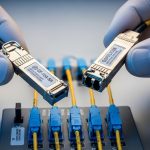
AI and ML infrastructure is unforgiving: one marginal optical link can throttle GPU utilization, trigger retransmits, and quietly inflate power and cooling costs. This article helps network and data center engineers choose high-performance transceivers for modern leaf-spine and fabric designs, focusing on the practical details that show up during installation and validation. You will get a Top 8 list of the most common “right fit” transceiver categories, plus a selection checklist and troubleshooting patterns seen in the field.
Top 1: 400G QSFP-DD for AI fabric uplinks (short reach)
For many AI clusters, the fastest path to consistent throughput is 400G QSFP-DD on short-reach optics, typically for leaf-spine uplinks where fiber runs are controlled. Engineers often deploy this when they need high port density and predictable latency across spine stages. In practice, you validate optics with vendor-qualified transceivers and verify lane mapping, since QSFP-DD uses multiple lanes aggregated to 400G.
Key specs to verify: wavelength (usually 850 nm for OM4/OM5 short reach), supported reach, lane rate, and DOM (digital optical monitoring). If your cabling is OM4 vs OM5, confirm the vendor’s maximum reach at your specific transceiver temperature class. Refer to [Source: IEEE Standards Association] for Ethernet optical interfaces context and to vendor datasheets for exact reach budgets. For optical fiber, also align with ANSI/TIA guidance on multimode link performance; see [Source: Telecommunications Industry Association].
Best-fit scenario: A 3-tier AI data center leaf-spine topology with 48-port 400G ToR switches, using 8–15 m OM5 links between leaf and spine. In commissioning, field teams typically run optical power and BER verification, then cross-check DOM thresholds in the switch telemetry dashboard.
- Pros: High port density, strong ecosystem, excellent suitability for multimode in controlled distances.
- Cons: Requires strict fiber quality and vendor qualification; higher module cost than 100G/200G.

Top 2: 300G QSFP56 DR4 for cost-optimized data hall links
When budgets tighten but you still need high throughput, 300G QSFP56 DR4 can be a practical compromise for mid-reach connectivity. DR4 typically uses four wavelengths or lanes depending on implementation, and it is often chosen when OM4/OM5 multimode reach is insufficient for a direct short-reach option. Engineers like this category because it can reduce per-port cost while maintaining predictable performance.
Key specs to verify: supported fiber type (MMF vs SMF), reach (meter range), connector type (LC is common), and whether the transceiver offers extended temperature operation (e.g., 0 to 70 C or -5 to 70 C depending on class). Confirm compatibility with your switch’s optics inventory and check whether the platform requires vendor-specific EEPROM behavior for DOM parsing. Use vendor datasheets and your switch hardware guide to avoid interoperability surprises.
Best-fit scenario: A training cluster where 300G is used for aggregation to a dedicated storage fabric, with 30–50 m links across equipment rows. Teams often keep these links in a “controlled patching zone” so MPO-to-MPO polarity and cleaning practices remain consistent.
- Pros: Better cost-to-capacity than many 400G short-reach options; good for mid-reach.
- Cons: Reach depends heavily on fiber plant and cleaning; migration paths may be less uniform than 400G/800G.
Top 3: 200G QSFP56 FR4 for longer multimode-to-single-mode planning
200G QSFP56 FR4 is frequently selected when you need longer reach than typical short-reach MMF, especially in mixed fiber plants. FR4 is commonly associated with single-mode fiber operation using multiple wavelengths; this makes it attractive for inter-rack or inter-row runs where pulling new fiber is expensive. For high-performance transceivers supporting AI/ML, the biggest win here is operational flexibility across existing cabling.
Key specs to verify: wavelength set, SMF reach at the vendor’s stated power budget, transmitter output power, receiver sensitivity, and optical safety class. Also confirm whether the module supports standard diagnostics (DOM) and whether it exposes temperature, bias current, RX power, and alarms in the same format your switch expects.
Best-fit scenario: A regional AI edge site where racks are separated by 60–120 m and retrofitting new fiber is delayed. Engineers deploy FR4 on SMF with an engineered budget and document the link loss including connectors, splices, and patch panels.
- Pros: Strong reach for SMF; helps extend AI fabrics without immediate fiber overhaul.
- Cons: Requires careful budget math and connector hygiene; some platforms are selective about optics vendors.
Top 4: 100G SFP28 SR for legacy compatibility and deterministic staging
Even in AI-first designs, 100G SFP28 SR remains useful for staging, brownfield upgrades, and deterministic testing phases. Many data centers still have SFP28-capable switches in test labs, staging closets, or older aggregation tiers. High-performance transceivers at 100G are also easier to validate because the ecosystem is mature and the failure patterns are well known.
Key specs to verify: 850 nm wavelength, reach for OM4 vs OM5, power consumption, and the temperature operating range. If you are using third-party optics, verify that DOM alarm thresholds and vendor-specific calibration do not cause false link flaps in your telemetry system.
Best-fit scenario: A lab-to-fabric migration where engineers run parallel tests: 100G SFP28 SR on OM4 for validation, then upgrade to 400G QSFP-DD for production. This reduces risk during cutovers because you can isolate optical issues from higher-speed lane mapping issues.
- Pros: Mature support, lower per-port cost, straightforward troubleshooting.
- Cons: Lower capacity density; may not meet future scaling targets without redesign.

Top 5: 10G SFP+ LR for management networks and out-of-band resilience
For AI/ML operations, the most critical traffic is not always the fastest. 10G SFP+ LR often underpins management planes, telemetry backhaul, and out-of-band resilience where you need stable connectivity across longer corridors. In many environments, these links are “always on,” so reliability and predictable behavior matter more than peak throughput.
Key specs to verify: 1310 nm wavelength, SMF reach, link budget assumptions, and whether the transceiver supports digital diagnostics. Also confirm whether your switch ports treat SFP+ optics differently under power cycles, because a few platforms require a reboot after optics EEPROM updates.
Best-fit scenario: A management network spanning 200 m between an AI training hall and a central monitoring room, using SMF with engineered loss and documented splices. Field teams regularly run lint-free cleaning checks and verify RX power against thresholds during quarterly maintenance.
- Pros: Excellent reach for management; stable and well-understood operational envelope.
- Cons: Not suitable for high-throughput data-plane scaling; depends on SMF plant quality.
Top 6: 25G SFP28 SR for flexible interconnects in dense GPU servers
25G SFP28 SR is a common building block for flexible interconnects, especially where you need to balance cost, density, and cabling simplicity. Many AI server designs use 25G for certain aggregation paths, and SFP28 simplifies patching compared with higher-capacity form factors that often rely on MPO harnesses. Engineers appreciate that you can stage upgrades port-by-port.
Key specs to verify: 850 nm SR behavior, reach on OM4/OM5, and whether the transceiver is rated for the chassis temperature profile. Confirm whether your platform supports the exact lane rate and modulation mode expected for 25G, and check optics compatibility lists where available.
Best-fit scenario: A GPU server rack with 12–16 servers aggregated into a ToR switch, using 25G SR on OM4 for 20–60 m runs. During deployment, teams standardize labeling and enforce cleaning protocols to avoid “works in the lab, fails in production” issues.
- Pros: Flexible and cost-effective; easier patching than many MPO-based options.
- Cons: May bottleneck at fabric scale if not paired with higher-speed uplinks.
Top 7: 50G/100G QSFP (Ethernet) for aggregation where QSFP cages are available
In some designs, QSFP form factors at 50G or 100G provide a practical middle ground between SFP+ and higher-capacity QSFP-DD. These are often used for aggregation where the chassis has QSFP cages and the cabling plant is already standardized on LC connectors. Engineers choose these high-performance transceivers to minimize chassis changes and maintain predictable power draw.
Key specs to verify: exact interface type (e.g., 50G Ethernet vs 100G), reach, connector type, and DOM support. Also validate whether your switch supports “breakout” modes that map lanes differently; misconfiguration can look like a bad optics problem when it is actually port mode selection.
Best-fit scenario: A mid-tier aggregation layer in a mixed-speed environment where 50G/100G QSFP ports are available and the cabling uses LC duplex. Teams standardize port-mode templates in automation to reduce human error.
- Pros: Good fit for mixed hardware generations; can reduce migration downtime.
- Cons: Compatibility depends on exact switch port capabilities; breakout modes add complexity.
Top 8: 800G OSFP for next-gen AI fabrics (reach varies by optics type)
For the most aggressive AI scaling, 800G OSFP is where you start planning beyond “just swap optics.” OSFP modules can be paired with different optical engines (short-reach vs longer reach variants), so you must select the optics type that matches your fiber plant. Engineers often treat 800G as a system-level project involving airflow, power budgeting, and link validation tooling.
Key specs to verify: OSFP module power, reach class, and the exact wavelength band for your selected variant. Confirm that your switch’s OSFP ports support the module’s required electrical interface and that your monitoring stack can interpret DOM and alarms reliably.
Best-fit scenario: A new build-out where the spine is upgraded to 800G and the leaf uplinks are upgraded accordingly, with MPO harnesses engineered for polarity and insertion loss. Teams run burn-in tests and BER sampling before full traffic cutover.
- Pros: Maximum throughput and future scaling headroom.
- Cons: Higher module cost and stricter validation; optics options depend heavily on switch generation.

Specs comparison that actually helps during procurement
Procurement teams often compare “reach” only, but installation success depends on connector type, power class, temperature rating, and DOM support. Below is a practical comparison across common high-performance transceiver categories used in AI/ML infrastructure. Always confirm exact parameters in the specific vendor datasheet and the switch compatibility matrix.
| Category | Typical Data Rate | Form Factor | Wavelength / Band | Connector / Fiber | Reach Class (typical) | Operating Temp (common) | DOM Support |
|---|---|---|---|---|---|---|---|
| Short-reach | 400G | QSFP-DD | 850 nm (MM) | MPO/MTP or LC (platform dependent), OM4/OM5 | Up to tens of meters | 0 to 70 C | Yes (vendor-specific alarms) |
| Cost mid-reach | 300G | QSFP56 | Variant (often MM) | Platform dependent, multimode | ~30 to 100 m class | -5 to 70 C (varies) | Yes |
| Longer reach | 200G | QSFP56 | FR4 (SM) | LC, SMF | Up to hundreds of meters (budget dependent) | 0 to 70 C | Yes |
| Legacy staging | 100G | SFP28 | SR 850 nm (MM) | LC duplex, OM4/OM5 | Up to ~100 m class (vendor dependent) | 0 to 70 C | Yes |
| Management resilience | 10G | SFP+ | LR 1310 nm (SM) | LC duplex, SMF | Up to ~10 km class | -40 to 85 C (varies) | Yes |
| Flexible aggregation | 25G | SFP28 | SR 850 nm (MM) | LC duplex, OM4/OM5 | Up to ~70 m class (vendor dependent) | 0 to 70 C | Yes |
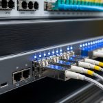
Pro Tip: In many AI facilities, the biggest causes of link instability are not “bad transceivers” but dirty MPO/LC endfaces and connector insertion loss drift after repeated patching. During acceptance testing, measure RX power and verify it stays comfortably above the vendor’s low-power threshold after you re-terminate or re-route any harnesses.
Selection criteria checklist engineers use before ordering
To choose high-performance transceivers that perform under load, engineers weigh tradeoffs in a repeatable order. This is the sequence that tends to prevent rework and reduce lead time risk.
- Distance and fiber type: Confirm OM4 vs OM5 vs SMF, then validate link loss including splices and patch panels.
- Switch compatibility: Use the platform’s optics compatibility list and verify port mode settings (especially for QSFP breakout).
- Reach budget and margin: Validate against vendor budgets, not marketing reach numbers; require margin for aging and temperature swings.
- DOM and telemetry integration: Ensure your monitoring stack can read DOM fields and that alarms map cleanly to thresholds.
- Operating temperature: Match the transceiver temperature class to your chassis airflow profile; check for derating behavior.
- Vendor lock-in risk: If you plan multi-year scaling, check multi-vendor support and whether the switch enforces strict EEPROM checks.
- Power and cooling impact: Compare module power draw and ensure the PSU and thermal design can absorb peak loads.
- Connector and cleaning workflow: Align with your operational ability to clean and inspect MPO/LC connectors reliably.
Common mistakes and troubleshooting patterns
Even experienced teams hit recurring failure modes when deploying high-performance transceivers for AI/ML