In low-latency financial trading networks, the wrong optics can quietly add microseconds that compound into missed fills. This article helps trading engineers and network architects compare HFT fiber optic transceivers—especially QSFP28 vs SFP+—through the lens of real deployment constraints: reach, switch compatibility, DOM behavior, and operating temperature. You will get practical troubleshooting patterns, a decision checklist, and a clear recommendation by reader type.

Latency reality check: what actually drives end-to-end delay in HFT
When teams say “low latency,” they often focus on optical reach and forget the rest of the chain: SerDes lane mapping, FEC mode, switch pipeline behavior, and even transceiver power state transitions. In practice, the optical module contributes a small but measurable portion of delay: transmitter laser modulation, receiver photodiode conversion, and serializer/deserializer processing. The dominant variable is often the switch datapath and whether the link is configured with forward error correction (FEC) or a non-FEC profile.
For HFT fiber optic links, you typically operate within IEEE Ethernet PHY families (for example, 10GBASE-SR, 25G/40G/100G families depending on platform). Vendors publish typical optical receive/transmit timing, but the field reality is that the “latency budget” should be measured in your topology with traffic generators and timestamping at the endpoints. A useful approach is to run controlled tests: lock link speed, disable/enable FEC intentionally, and compare the delta at the application layer under identical switch load.
QSFP28 vs SFP+ latency: where the difference shows up
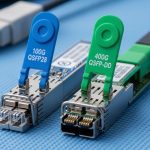
SFP+ modules commonly target 10GBASE-SR using short-reach multimode (MMF) or sometimes DAC/AOC for very short runs. QSFP28 targets 25G Ethernet over fiber, often used for higher bandwidth aggregation with similar rack-scale distances. The latency difference is rarely “QSFP28 is always faster.” Instead, it depends on the switch ASIC pipeline, how the platform implements 25G vs 10G, and whether the optics negotiation selects the expected mode.
Pro Tip: In HFT environments, measure latency with the exact same link profile you will run in production, including FEC settings and any vendor-specific “energy efficient” or “power saving” modes. Even when two transceivers are “same reach,” a different FEC mode can introduce additional processing delay that dwarfs optics-only timing.
Performance and specifications: comparing optics for short-reach trading links
Short-reach HFT fiber optic design usually targets rack-to-rack or pod-to-pod distances using multimode fiber (MMF) to reduce cost and complexity. Your selection should start with the wavelength, reach class, and connector type, then align with the switch port’s supported PHY and optics type. For example, 10GBASE-SR and 25GBASE-SR are common for low-latency fabrics, while single-mode variants can be used for longer metro segments or when MMF plant is unavailable.
Key spec comparison table (typical SR optics)
| Spec | SFP+ 10GBASE-SR (MMF) | QSFP28 25GBASE-SR (MMF) |
|---|---|---|
| Data rate | 10.3125 Gb/s (10GBASE-SR) | 25.78125 Gb/s (25GBASE-SR) |
| Wavelength | Commonly 850 nm VCSEL | Commonly 850 nm VCSEL |
| Reach class | Typically 300 m (OM3) / 400 m (OM4) (depends on vendor) | Often 100 m (varies by module and fiber) |
| Connector | LC duplex (most SR modules) | LC duplex (most SR modules) |
| DOM support | Usually supported via SFP MSA (temperature, voltage, bias, optical power) | Usually supported via QSFP MSA (digital diagnostics) |
| Operating temperature | Commonly 0 to 70 C (commercial) or -40 to 85 C (extended) | Commonly 0 to 70 C or -40 to 85 C depending on SKU |
| Form factor | SFP+ (1x optical channel) | QSFP28 (typically 4x lanes aggregated) |
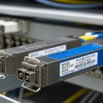
Concrete module examples you will see in trading networks
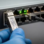
On the 10G side, common optics include Cisco-branded and third-party SFP+ SR modules such as Cisco SFP-10G-SR, and compatible 850 nm SFP+ optics from vendors like Finisar and FS. On the 25G side, QSFP28 SR modules are widely deployed, with examples such as Finisar/other vendor QSFP28 25G SR SKUs and FS.com QSFP28 SR variants (always verify OM support and reach in the datasheet for your fiber plant).
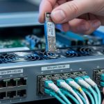
Always cross-check with the vendor datasheet and your switch transceiver compatibility list. In high-availability trading setups, “it links at all” is not enough; you need stable link margins under temperature swings and realistic fiber insertion loss.

Compatibility and negotiation: the hidden failure mode in low-latency fabrics
Even if two optics are “both 850 nm SR,” they can behave differently during link bring-up due to how the module reports capabilities and how the switch configures the PHY. Most modern platforms rely on digital diagnostics (DOM) and standardized identification (EEPROM data) to validate the optics. If a third-party module lacks correct identification, the switch may run the port in a fallback mode with different equalization parameters or even refuse the module.
For HFT fiber optic deployments, compatibility also includes operational details: whether your switch supports the exact data rate (10G vs 25G), whether it supports the required FEC profile, and whether it can maintain stable link under high utilization. Some platforms also apply different buffer management strategies per speed class, affecting latency variance even if average latency looks similar.
DOM and monitoring: what operations teams should validate
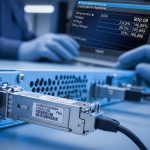
Field engineers typically watch DOM values continuously: transmit power, receive power, module temperature, and sometimes bias current. For example, if receive power is near the module’s sensitivity threshold, the link may remain “up” but error counters can rise with temperature or connector contamination. In trading networks, this can show up as increased retransmissions or microbursts of loss, which are catastrophic for order book synchronization.
Cost and ROI: when third-party optics win and when they backfire
Optics pricing in trading environments is not just “module cost.” It is the sum of module price, spares inventory, failure rates, downtime risk, and the engineering time spent validating compatibility. In many datacenters, a third-party SFP+ or QSFP28 SR module can be materially cheaper than OEM. However, ROI can invert if the platform rejects the module, if link stability requires frequent swaps, or if monitoring tooling cannot interpret DOM reliably.
Typical street pricing (ballpark) for SR optics varies widely by vendor and temperature grade. You might see commercial-grade 10G SR SFP+ modules in a lower-cost band versus OEM-branded modules, while QSFP28 25G SR modules generally cost more per port due to higher speed and module complexity. TCO should include: (1) the cost of holding spares, (2) the labor cost of maintenance windows, and (3) the “risk premium” for optics that behave differently across firmware revisions.
Decision matrix: pick based on your constraints
| Criterion | Choose SFP+ 10GBASE-SR when… | Choose QSFP28 25GBASE-SR when… |
|---|---|---|
| Distance | Your MMF plant supports the needed SR reach with margin | You need higher bandwidth but still stay within SR reach limits for your fiber type |
| Latency variance | Your switch ASIC pipeline behaves predictably at 10G and you can disable unwanted features | Your platform’s 25G datapath is stable and you have measured end-to-end latency under load |
| Budget | You want lower optics cost and simpler scaling to many ports | You accept higher per-module cost to reduce oversubscription and improve throughput |
| Switch compatibility | OEM or validated third-party SFP+ modules are known-good for your exact switch model/firmware | OEM or validated QSFP28 modules are known-good for your switch model/firmware |
| DOM/telemetry | Monitoring stack works and DOM values are consistent across modules | Monitoring stack supports QSFP DOM fields and your tooling thresholds are tuned |
| Vendor lock-in risk | You can tolerate OEM bias or you have multiple validated suppliers for SFP+ | You mitigate lock-in by qualifying at least two sources and pinning module part numbers |
Selection criteria checklist for HFT fiber optic transceivers
Use this ordered checklist during qualification. It matches how teams actually reduce risk before committing modules to a production trading floor.
- Distance and fiber type: confirm MMF grade (OM3 vs OM4 vs OM5) and verify reach and link margin in datasheets.
- Switch compatibility: validate module support for your exact switch model and firmware revision; confirm speed negotiation (10G vs 25G) and any FEC mode.
- DOM and monitoring: confirm DOM is readable by your telemetry stack; set alert thresholds for temperature, receive power, and error counters.
- Operating temperature: trading floors can see airflow hotspots; choose extended temperature SKUs when needed (verify -40 to 85 C availability if your environment demands it).
- Operating mode stability: test under realistic load and link toggling; watch for link flaps and CRC/FEC error counters.
- Vendor lock-in risk: qualify at least one compatible third-party option and keep a pinned bill of materials to avoid silent changes.
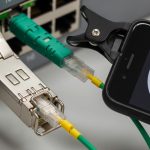
- Connector and plant health: validate cleaning process, insertion loss budget, and endface inspection results before blaming the module.

Common mistakes and troubleshooting tips in HFT optics
Most optics incidents in low-latency trading networks come from operational causes, not from “bad lasers.” Here are concrete failure modes you can recognize quickly.
Link comes up but errors climb under load
Root cause: insufficient optical power margin due to dirty connectors, high insertion loss, or a mismatch between module reach assumptions and your actual MMF grade. Solution: inspect and clean both ends, measure end-to-end loss with an OTDR or certified tester, and compare reported receive power against vendor thresholds.
Module is rejected or falls back to an unexpected mode
Root cause: incorrect EEPROM identification, unsupported DOM fields, or switch firmware that enforces a compatibility list. Solution: use vendor-validated part numbers for your switch model; update firmware only after re-qualification; confirm port speed and FEC settings after link-up.
Latency spikes coincide with temperature changes
Root cause: module temperature rising above the “stable” region, or thermal airflow differences between racks. VCSEL bias and receiver sensitivity can drift, increasing error bursts. Solution: monitor module temperature and receiver power; improve airflow, consider extended temperature SKUs, and retest latency under thermal conditions.
“We swapped optics and it was worse” during maintenance
Root cause: inconsistent cleaning/handling during swap; dust accumulation is often the real culprit. Solution: adopt a strict connector handling SOP: caps on every transceiver, controlled wipe procedure, and endface inspection before insertion.
Which option should you choose?
If you are optimizing for simplicity, many trading floors start with SFP+ 10GBASE-SR when the fiber plant and switch datapath are proven stable at 10G and when your bandwidth needs fit within 10G per link. If you need more throughput without redesigning the entire plant, QSFP28 25GBASE-SR is often the better scaling move, but only after you confirm the switch pipeline and FEC profile do not increase latency variance.
Recommendation by reader type: If you are a small team with limited change windows, qualify one or two validated module part numbers per switch model and stick to them. If you run a high-scale fabric with strict monitoring, qualify both SFP+ and QSFP28 options and choose based on your measured end-to-end latency, not just vendor “typical” timing.
FAQ
Q: What does “HFT fiber optic” mean in practice?
A: It is shorthand for optics used in high-frequency trading networks where latency variance and link stability matter as much as average delay. Practitioners qualify modules by measuring end-to-end performance in the real topology, not only by reviewing reach specs.
Q: Are QSFP28 links always lower latency than SFP+?
A: Not automatically. Latency depends heavily on the switch ASIC datapath, configured PHY features like FEC, and how the platform handles 25G vs 10G traffic. Always validate with timestamps at the endpoints under realistic load.
Q: Can I use third-party optics for HFT?
A: Often yes, but only after qualification for your exact switch model and firmware. Confirm DOM readability, stable link bring-up, and consistent error counters across temperature ranges.
Q: How do I choose between OM3 and OM4 for SR modules?
A: Use your actual link distance and insertion loss budget. If you need headroom for connector loss and aging, OM4 typically provides better performance margin for 850 nm SR optics, but confirm vendor reach claims for your exact module SKU.
Q: What should we monitor besides link up/down?
A: Track module temperature, transmit and receive optical power, and Ethernet error counters (CRC, FEC-related counters if applicable). Latency-sensitive apps can degrade even when the link state remains “up.”
Q: Where can I verify standards and module behavior?
A: Start with IEEE Ethernet PHY references like IEEE 802.3 for 10G/25G Ethernet PHY behavior and vendor datasheets for specific optics timing and reach. Also consult your switch vendor’s transceiver compatibility guidance. IEEE 802.3 [Source: IEEE 802.3]
Update date: 2026-04-30.
Author bio: I build and validate low-latency network paths end-to-end, focusing on measurable latency variance and operational reliability. I help teams reach PMF by running fast, controlled qualification loops for hardware like optics and switching fabrics.