Underground mining networks fail for reasons that look unrelated at first: condensation, vibration, dust ingress, and power cycling that quietly degrade optics. This article helps network and field engineers select the right harsh environment transceiver when using SFP modules for underground communication. You will get practical selection criteria tied to real deployments, plus troubleshooting steps for the failure modes that show up in mines.
Why underground mining SFP links demand a harsh environment transceiver
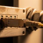
In mining, the transceiver is only one part of a fiber system, but it is often the earliest component to show stress. SFP optics face elevated temperature swings, mechanical shock, and frequent link resets caused by switch reboots during maintenance windows. In parallel, fiber plant conditions can be harsher than “office-grade” assumptions: higher bend radius violations during install, moisture migration in splice enclosures, and abrasive dust exposure during patching.
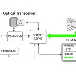
From a standards perspective, most SFP behavior is defined by the SFP Multi-Source Agreement for electrical interfaces and management, while Ethernet PHY behavior follows IEEE 802.3 clauses for link signaling and optical power budgets. In practice, you confirm compatibility by matching data rate, optical wavelength, and DOM (Digital Optical Monitoring) support to the switch vendor’s optics qualification list. For underground use, you also verify environmental qualifications in the vendor datasheet, not just the transceiver’s link performance on paper.
Environmental stressors that impact optics performance
- Thermal cycling: repeated heat-up and cool-down changes laser bias current and can increase optical output drift.
- Condensation: moisture can corrode contacts or affect board-level sealing, leading to intermittent CRC errors.
- Vibration and shock: movement can loosen fiber patching or alter connector seating, producing marginal optical budgets.
- EMI and grounding variability: affects SFP host electrical interface stability, especially in long or noisy backplanes.

Key SFP optical specs that determine underground link success
Underground mining links often run longer than typical enterprise patching, but shorter than some campus backbones. The correct harsh environment transceiver selection starts with the optical reach class and then tightens the budget using measured link loss. You should treat “reach” as a maximum envelope and then apply margin for splice loss, connector loss, aging, and worst-case temperature effects.
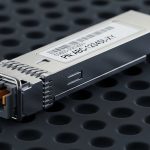
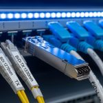
For SFP, the most common underground choices are 1G or 10G optics over multimode (MMF) or single-mode (SMF). If your mine uses legacy copper for short spans, SFP optics can still serve as rugged consolidation points at fiber distribution points. You must also consider connector type, because field re-termination errors on LC connectors are a frequent root cause of intermittent link drops.
| Spec | Typical SFP Option | What to Verify for Mining |
|---|---|---|
| Data rate | 1G SFP (GbE) or 10G SFP+ (10GbE) | Switch port speed support and auto-negotiation behavior; confirm no forced-mode mismatch |
| Wavelength | 850 nm (MMF) or 1310/1550 nm (SMF) | Match fiber type and dispersion tolerance; ensure wavelength matches transceiver pairing |
| Reach | 850 nm: up to ~300 m on OM3/OM4 (depends on optics); SMF: multiple km | Apply link budget with measured attenuation and worst-case splice/connector loss |
| Connector | LC (common for SFP) | Confirm LC connector grade and dust caps; verify field cleanliness procedures |
| DOM | Supported in many 1G/10G SFPs | Confirm switch reads DOM thresholds; use it for preventive maintenance |
| Operating temperature | Commercial often 0 to 70 C; industrial often wider; some rugged designs support extended ranges | Validate for the enclosure location: tunnel service rooms vs equipment cages |
| Optical power | TX power and RX sensitivity vary by class | Confirm link budget margin under dust, aging, and temperature drift |
Real-world link budget approach
In underground fiber, you rarely get to assume “average” losses. A field approach is to measure end-to-end attenuation using an OTDR or power meter at install, then add a conservative margin for future connector maintenance. For example, if your splice enclosure measurement shows 0.6 dB total insertion loss across splices and connectors and your transceiver budget allows 3.5 dB for margin, you can maintain a safe operating window only if your worst-case bending and aging stay within that margin. When you cannot measure during installation, choose optics with more reach headroom than you think you need.
Pro Tip: In mines, intermittent link drops are often not “optics death” but connector micro-misalignment caused by vibration after patch-panel access. Enabling DOM and correlating RX power swings with shift-level maintenance events can reveal this pattern before CRC errors become a full outage.
Matching SFP modules to mine switch behavior and DOM monitoring
Even when an SFP meets optical specs, underground operations can fail at the management layer. Many switches read DOM values (temperature, bias current, TX power, RX power) and apply internal alarms or even shut down ports if thresholds are exceeded. If you select a harsh environment transceiver that reports DOM values differently than the switch expects, you can see nuisance alarms or delayed detection of real degradation.
Start with the switch model and firmware release, then check the vendor’s optics compatibility guidance. If you use third-party SFPs, confirm that the switch supports that transceiver’s DOM implementation and that the module’s EEPROM fields match the expected format. For network management, define where alarms should go (NMS, syslog, SNMP traps) and what action triggers a field visit.
Deployment scenario: 10G leaf-spine to underground aggregation
Consider a 3-tier mine network: 48-port 10G ToR switches at surface, aggregation at a service room, and multiple underground distribution points connected via fiber. Suppose each underground branch uses 10G SFP+ over single-mode fiber with 2.5 km average distance and about 1.2 dB measured total loss from splices and connectors. Engineers typically deploy rugged 10G optics with DOM so they can monitor RX power, and they schedule maintenance windows every 90 days to inspect patch panels. In this environment, selecting optics with adequate link margin and verified DOM compatibility reduces unplanned downtime, because you can detect a slow RX power decline before the link falls below sensitivity.

Selection criteria checklist for harsh environment transceiver procurement
When buying for underground SFP deployment, the biggest mistakes are usually not optical reach miscalculations but procurement and compatibility gaps. Use this ordered checklist to reduce risk across distance, budget, and operational fit.
- Distance and fiber type: confirm SMF vs MMF, measured attenuation, and worst-case connector count; verify wavelength compatibility (850 vs 1310/1550).
- Optical budget with margin: compute TX power minus RX sensitivity minus measured loss; add margin for future re-termination and aging.
- Switch compatibility: validate the SFP family with your switch model and firmware; confirm port speed and any breakout constraints.
- DOM support and thresholds: ensure the switch reads DOM; configure alarms for RX power drift and temperature excursions.
- Operating temperature and enclosure reality: do not rely on “module max” only; account for the equipment cage airflow and tunnel ambient conditions.
- Mechanical and environmental qualification: confirm shock/vibration and ingress protection claims are relevant to your mounting and enclosure.
- Connector and handling ecosystem: LC geometry, dust caps, and field cleaning tools availability often matter as much as optics.
- Vendor lock-in risk: assess support model, replacement lead time, and whether third-party optics are accepted under your maintenance plan.
- Power and TCO: estimate power draw per port, failure rates, and warranty terms; include labor costs for swaps in constrained tunnel access windows.
Cost and ROI note for mine operations
Pricing varies sharply by data rate and qualification level. In many markets, OEM SFP modules can cost roughly $150 to $400 per unit for 10G class rugged/qualified options, while third-party modules might range $60 to $200 depending on DOM and reach. The ROI calculation should include the cost of a failed port swap: if tunnel access requires a 2-person team and a half-day window, labor can exceed the transceiver cost by multiple times. Over a 3 to 5 year lifecycle, selecting optics with better environmental qualification and reliable DOM can reduce truck rolls and reduce time spent diagnosing intermittent issues.
Common mistakes and troubleshooting in underground harsh optics
Field failures tend to cluster into a few patterns. Below are concrete pitfalls with root causes and practical solutions used by teams maintaining underground fiber plants.
Link flaps after patch-panel access
Root cause: vibration loosens an LC connection or dust contamination increases insertion loss, pushing RX power near sensitivity. DOM may show RX power oscillations even when TX power looks stable.
Solution: re-seat connectors with clean caps, inspect using fiber scope where available, and verify bend radius compliance near the cabinet. Add a DOM-based alarm for RX power drop-rate rather than only absolute thresholds.
“Wrong optics” that pass basic tests but fail under temperature
Root cause: selecting optics with marginal optical budget or mismatched wavelength class (for example, expecting 1310 nm behavior but using an incompatible transceiver family). In temperature swings, laser output drift reduces margin.
Solution: confirm wavelength and reach class against the datasheet and verify the end-to-end budget using measured loss. If you cannot measure, pick optics with extra headroom and document the assumption.
Nuisance alarms or port disable events due to DOM mismatch
Root cause: switch firmware interprets DOM fields differently or applies strict alarm thresholds that third-party optics report outside expected ranges.
Solution: validate with your exact switch model and firmware in a controlled test bed before underground rollout. If needed, tune monitoring thresholds through the switch management interface and document the change for audits.
OTDR shows no major faults, but CRC errors persist
Root cause: micro-bends or poor connector polish can create high-frequency impairments not obvious on coarse loss measurements. Also, dirty connectors can produce intermittent errors even if average power looks acceptable.
Solution: re-clean and re-terminate suspect connectors, then correlate CRC error counters with link flaps and DOM RX power trends. Use a fiber inspection scope and verify polish grade.

Standards and vendor datasheet checks that reduce risk
To keep procurement grounded, reference the relevant Ethernet PHY behavior and SFP interface expectations. For Ethernet link characteristics, IEEE 802.3 provides baseline for 10G and 1G optical interfaces and signaling behavior; for SFP form factor and electrical interface constraints, consult the SFP Multi-Source Agreement materials and vendor implementation notes. Then, align those expectations with the optics datasheet: confirm TX power, RX sensitivity, DOM accuracy, and environmental operating temperature range.
When you evaluate a harsh environment transceiver, insist on documented parameters rather than only marketing claims. If a datasheet lacks shock/vibration context or provides an operating range that assumes controlled airflow, treat it as a risk for tunnel installations where airflow is inconsistent.
Authority references you can use during selection: [[EXT:https://standards.ieee.org/standard/802_3 IEEE 802.3]] for Ethernet behavior and [Source: IEEE 802.3] plus vendor datasheets for DOM and environmental ratings. For practical optics qualification discussions, also review vendor interoperability notes and optics compatibility guides published by switch manufacturers, such as Cisco SFP compatibility documentation where applicable. [Source: Cisco Optics Compatibility Documentation]
FAQ
What makes a transceiver “harsh environment” for mining?
In practice, it means environmental qualification beyond basic commercial assumptions, plus reliable DOM behavior and robust handling characteristics. You should verify operating temperature range, documented shock/vibration support, and realistic enclosure guidance in the datasheet.
Should I use 850 nm or 1310/1550 nm SFPs underground?
Choose based on fiber type and distance. 850 nm SFPs are common for shorter MMF runs, while 1310/1550 nm are typical for SMF over longer distances and better reach headroom.
How do I calculate whether the optics will survive real losses?
Use a measured link budget: TX power minus RX sensitivity minus measured insertion loss. Then add margin for connectors, splices, and expected aging, and confirm temperature drift does not consume the remaining margin.
Will DOM help prevent outages in a mine?
Yes when you actually operationalize it. Correlate DOM RX power and temperature trends with error counters so maintenance can happen before the link falls below sensitivity thresholds.
Are third-party SFPs safe for underground deployments?
They can be, but only after compatibility validation with your switch model and firmware. The main risk is DOM interpretation differences or slightly different optical power characteristics that reduce margin under temperature swings.
What is the first thing to check when links flap?
Check DOM RX power for oscillation and inspect connector seating and cleanliness near the cabinet. In mines, micro-misalignment after vibration or dust exposure is a frequent root cause even when OTDR shows no major attenuation events.
If you want to standardize your underground optics program, start by building a link budget template and DOM alarm policy, then validate module compatibility in a controlled test rack. Next, review fiber connector cleaning and inspection practices to reduce the most common field-induced failures.
Author bio: I have deployed fiber networks in industrial and underground sites, including switch-to-cabinet architectures with DOM-based monitoring and OTDR-driven acceptance testing. I also support field teams on optics diagnostics, connector failure analysis, and interoperability validation across OEM and third-party SFP inventories.