You are planning a metro upgrade where every 10G or 25G hop must stay stable, yet the budget is already stretched. This article helps network engineers and data center operations teams compare gray optics colored optics transceiver choices for span-by-span reliability, optics power budgets, and day-two maintenance. You will get practical decision criteria, a troubleshooting checklist, and an ROI view that reflects field realities like DOM behavior and interoperability.
Why “gray” vs “colored” optics matters in metro networks
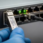
In most metro designs, the transceiver is less about aesthetics and more about link discipline: wavelength accuracy, optical power, receiver sensitivity, and how vendors implement diagnostics. “Gray optics” commonly refers to OEM-style SFP or SFP28 modules with a gray housing and standardized electrical interfaces, while “colored optics” often refers to modules whose housings are colored to indicate type or vendor ecosystem. The critical point is that “gray” or “colored” is typically a visual cue; the real behavior comes from the optical standard (for example IEEE 802.3), the fiber type, and the module’s transmitter/receiver characteristics.
Metro networks add extra stress: you may have tighter operational windows, more patch panel rework, and mixed vendor optics across multiple sites. A field engineer often sees “mystery” link flaps after a swap because the new module meets the spec on paper but differs in DOM thresholds, cable plant assumptions, or temperature class. The safest approach is to treat the color as a starting hint, then verify wavelength, reach class, and diagnostic support against the switch vendor’s compatibility guidance.
Standards and what they actually constrain
Ethernet over fiber is governed by IEEE 802.3 clauses for electrical lanes and optical interfaces. For example, 10GBASE-SR and 10GBASE-LR define optics behavior, while 25GBASE-SR and 25GBASE-LR define higher lane rates and optical parameters. In practice, vendor datasheets translate those standards into concrete values like nominal wavelength (nm), transmit power (dBm), and receiver sensitivity (dBm). For metro planners, the optical link budget and fiber plant quality dominate outcomes more than housing color.
For diagnostics, many modules implement Digital Optical Monitoring (DOM) over the standardized management interface. While DOM is widely used, exact threshold values and supported diagnostic registers can vary by vendor, which can affect how a switch interprets “warning” versus “fault.” Source: IEEE 802.3

Key specifications that decide link success (not color)
When teams compare a gray optics colored optics transceiver choice, the winning modules are the ones that match your metro link budget and switch expectations. For short-reach metro segments (typical 10G/25G over multimode), the critical variables are fiber type (OM3 vs OM4), modal bandwidth, and launch conditions. For longer metro segments (often single-mode), the key variables are wavelength class (for example 1310 nm vs 1550 nm), transmitter power, receiver sensitivity, and connector cleanliness.
The table below compares representative module families you might actually deploy in metro environments. Values vary by exact part number, but the categories show what engineering teams should verify before ordering. Always confirm with the vendor datasheet for the exact model and temperature grade.
| Spec | 10GBASE-SR (MMF, typical) | 10GBASE-LR (SMF, typical) | 25GBASE-SR (MMF, typical) | 25GBASE-LR (SMF, typical) |
|---|---|---|---|---|
| Data rate | 10.3125 Gbps | 10.3125 Gbps | 25.78125 Gbps | 25.78125 Gbps |
| Wavelength | 850 nm | 1310 nm | 850 nm | 1310 nm |
| Reach class (typical) | 300 m to 400 m on OM3/OM4 | 10 km on SMF | 100 m to 400 m (OM3/OM4, depends on module) | 10 km on SMF |
| Connector | LC | LC | LC | LC |
| Tx power | ~ -5 to 0 dBm (varies) | ~ -8 to 0 dBm (varies) | ~ -5 to +2 dBm (varies) | ~ -8 to +2 dBm (varies) |
| Rx sensitivity | ~ -11 to -14 dBm (varies) | ~ -14 dBm (varies) | ~ -11 to -15 dBm (varies) | ~ -14 dBm (varies) |
| DOM support | Common; verify register set | Common; verify register set | Common; verify register set | Common; verify register set |
| Temperature range | 0 to 70 C or industrial -40 to 85 C | 0 to 70 C or industrial -40 to 85 C | 0 to 70 C or industrial -40 to 85 C | 0 to 70 C or industrial -40 to 85 C |
Concrete part-number examples engineers reference
In metro rollouts, procurement teams often start with known compatibility targets. For instance, you may see enterprise and access networks using Cisco-compatible optics such as Cisco SFP-10G-SR or Cisco SFP-10G-LR variants (exact ordering numbers differ). On the optics bench, third-party suppliers also publish detailed datasheets for modules like Finisar FTLX8571D3BCL (25G/10G family varies by exact suffix) or FS.com SFP-10GSR-85 (example naming for 850 nm short reach). The practical takeaway is not the brand, but the fact that each part number encodes a specific optical budget and diagnostic behavior—so verify the exact model, not just the color or family name.
When comparing gray optics colored optics transceiver options, ask: does the module meet the switch’s required optical power range and DOM expectations? Many vendors provide compatibility lists or minimum DOM behavior notes in their switch documentation. Source: Cisco Technical Support

Field scenario: choosing optics for a metro leaf-spine upgrade
Consider a metro aggregation network connecting three sites in a ring: Site A, Site B, and Site C, each with 48-port 10G ToR switches feeding two 100G uplinks. The design uses 25G uplinks between aggregation pairs, with one segment at 2.5 km single-mode and another at 450 m multimode. The team plans a maintenance window of 4 hours per site and budgets for 40 new transceivers plus spares.
In this environment, the gray optics colored optics transceiver decision shows up at day-two operations. If a colored-housing module from a different vendor reports DOM thresholds differently, the switch might log “optical power low” warnings even when the link is healthy, creating alert fatigue. Conversely, a gray housing module that matches the same standard but lacks full DOM compatibility can be treated as “unsupported,” which sometimes blocks certain vendor-specific telemetry features. For stability, engineers typically standardize on one optics vendor family per switch model, then keep a matched spare set with the same DOM behavior.
During rollout, a field engineer measures optical power at the far end using the link budget assumptions plus a handheld power meter and verifies connector cleanliness with a scope before inserting modules. Even the best module will fail if the patch panel has dust or if the fiber polarity is reversed on duplex LC. In practice, “color” rarely fixes these issues; disciplined handling does.
Pro Tip: In metro installs, the most time-consuming optics failures are often not optical budget misses but DOM interpretation differences. Before ordering in volume, run a 24-hour burn-in test on the exact switch model and confirm that the transceiver reports the same temperature and bias-current register ranges your monitoring system expects.
Selection checklist for gray vs colored optics in metro
Engineers rarely choose by housing color alone. They choose by repeatability: the same module behavior across sites, predictable alarms, and an optical budget that survives aging and connector rework. Use this ordered checklist during procurement and pre-ship validation.
- Distance and fiber type: confirm OM3 vs OM4 vs SMF, and verify reach class against your measured span, patch count, and splice loss.
- Switch compatibility: check the switch vendor’s optics compatibility matrix for the exact transceiver class (SFP28 vs SFP+ vs QSFP28) and supported DOM behavior.
- Wavelength and standard match: ensure the module is truly compatible with the Ethernet PHY requirement (for example SR vs LR), not just “looks similar.”
- DOM support and telemetry: validate that your monitoring stack reads Tx/Rx power and temperature registers without false alarms.
- Operating temperature and derating: metro rooms can swing; select modules with the right temperature class and consider derating curves.
- Connector and polarity discipline: verify LC cleanliness and polarity labeling to avoid swapped transmit/receive fibers.
- Vendor lock-in risk: if you must standardize, plan a second approved vendor for spares to reduce outages during supply shocks.
How to compare “gray” and “colored” pragmatically
Ask whether the colored housing indicates a different internal optical engine or merely a different casing. If both modules claim the same IEEE-defined behavior and the same reach class on the same fiber type, then “gray” vs “colored” is mostly about supply chain consistency and DOM/telemetry alignment. Where differences matter is when one module family uses a distinct diagnostic implementation or slightly different Tx/Rx power targets that push the link closer to the sensitivity floor.
Common mistakes and troubleshooting tips
Metro optics failures can look random, but they usually have a root cause you can reproduce. Below are frequent mistakes a field team sees when swapping gray optics colored optics transceiver modules across sites, plus the most direct fixes.
Link comes up briefly then flaps after a swap
Root cause: optical power budget is marginal due to underestimated patch panel loss, dirty connectors, or an incorrect reach assumption (for example using OM3 expectations on a mixed OM3/OM4 plant). Solution: clean connectors with proper fiber cleaning tools, verify with a scope, and measure received power at the far end; then recalculate budget with measured splice and patch losses.
Switch logs “unsupported transceiver” or disables the port
Root cause: DOM or electrical identification fields do not match what the switch expects for that module class, even if the optical wavelength is correct. This happens when the optics vendor’s EEPROM layout or diagnostic thresholds differ. Solution: use the switch vendor compatibility list for that exact model number; run a pre-approval test and confirm port state behavior before rolling out.
Telemetry shows constant low Tx power warnings while the link is still stable
Root cause: DOM scaling or threshold mapping differences cause monitoring systems to interpret normal values as warnings. Solution: compare DOM register readouts (temperature, bias current, Tx power, Rx power) between the old known-good module and the new module; update alert thresholds only after confirming optical health with a scope and measured power.
No light detected after installation despite correct wavelength
Root cause: duplex LC polarity reversal or swapped fibers in the patch panel. Solution: verify polarity labeling at both ends, correct the fiber mapping, and confirm optical continuity using a visual tracer or a proper optical test method.
Cost, TCO, and ROI notes for metro optics
In the real world, the cost difference between gray optics colored optics transceiver options is usually a function of qualification level, DOM implementation maturity, and supply chain stability—not the housing color itself. OEM optics often cost more upfront, but they can reduce troubleshooting time because compatibility behavior is well documented. Third-party modules can be cheaper, yet you must budget engineering time for validation, monitoring calibration, and occasional returns.
Typical street pricing for 10G SR and LR modules often lands in the range of $30 to $120 per unit depending on vendor and reach, while 25G optics and QSFP-class modules can range broadly, sometimes $100 to $350+. Over a metro lifecycle, TCO depends on failure rates, mean time to replace, and the cost of maintenance windows. If a module triggers frequent “warning” alarms, the operational tax can exceed the purchase price difference through engineer time and automated ticket volume.
ROI is strongest when you standardize on one optics family per switch model and keep a matched spare set. That reduces variability, minimizes DOM-related alert noise, and shortens incident response. If you plan multi-vendor redundancy, test both in the same switch environment before committing.

FAQ
What does “gray optics” mean compared to “colored optics”?
“Gray” or “colored” often describes module housing appearance and sometimes a vendor family. The real determinant is the optical standard and the module’s datasheet values for wavelength, reach, transmit power, and receiver sensitivity. Always confirm compatibility and DOM behavior with your switch model.
Can I mix gray and colored optics on the same metro link?
You can often mix modules if they are the same optical type (for example both SR or both LR) and meet the switch’s compatibility requirements. However, mixing vendors can change DOM thresholds and monitoring interpretation, which may create warnings or unsupported states. Validate in a staging environment before broad deployment.
Do colored optics indicate better performance?
Not inherently. Performance is governed by the underlying optical engine and the standard class, not the color of the housing. Two modules with the same reach class can still differ slightly in power targets, which matters when you are near the sensitivity margin.
How do I verify the optical budget for metro spans?
Start with the module’s Tx power and Rx sensitivity from the datasheet, then subtract fiber attenuation plus connector and splice losses. Use measured values when possible and include a margin for aging and rework. For multimode, confirm OM3 vs OM4 and the patch panel losses carefully.
Why do some optics trigger DOM warnings even when links are stable?
DOM readings and thresholds can be mapped differently across vendors and switch monitoring software. The link may be operating within spec while the monitoring system interprets the values as “low.” Compare DOM register readouts between a known-good module and the new module, then adjust thresholds only after confirming optical health.
What is the safest next step before ordering optics for a metro rollout?
Pick the exact module part numbers and run a 24-hour validation on the specific switch model, including DOM telemetry checks and optical cleaning verification. Confirm that alarms, port state, and throughput remain stable across environmental conditions. Then standardize purchases around the validated set.
Gray optics colored optics transceiver choices succeed when you treat color as a hint and verify the optical engine, DOM behavior, and switch compatibility with measured link budgets. Next, compare optics by standard class and reach using related topic so your metro upgrades stay quiet, predictable, and economically defensible.
Author bio: I have deployed SFP and QSFP optics across metro and data center fabrics, validating link budgets with field measurements and DOM telemetry. I write from hands-on troubleshooting experience with switch compatibility quirks and real connector-cleanliness failures.