When your Google Cloud Dedicated Interconnect circuit is delayed by optics mismatches, the root cause is often a wrong fiber transceiver selection rather than carrier provisioning. This article helps network engineers and field technicians choose the right `GCP fiber module` for Dedicated Interconnect by mapping common transceiver families to operational constraints like wavelength, reach, DOM behavior, and connector standards. You will also get a decision checklist, real deployment notes, and troubleshooting steps for the failure modes seen in racks, handholes, and patch panels.

How Dedicated Interconnect optics requirements translate to a GCP fiber module
Dedicated Interconnect uses Ethernet over fiber, so the optics must satisfy the electrical and optical layer expectations of the circuit. In practice, the “module fit” problem becomes a set of deterministic checks: correct data rate, correct wavelength (for example, 1310 nm vs 1550 nm families), correct reach for the actual installed link budget, and correct connector type at both ends. Most engineers start with the switch or router transceiver form factor, then work backward from the physical plant (fiber type, attenuation, and splice quality).
For compatibility, the key is not only “does it light up,” but “does it negotiate and remain stable under temperature and launch power limits.” Many enterprise switches rely on vendor-specific transceiver management details via digital optical monitoring (DOM) and EEPROM fields. If the DOM implementation is incomplete or out of tolerance, the port may stay in a disabled state or show intermittent link flaps.
Authoritative baselines come from IEEE Ethernet PHY definitions (for example, IEEE 802.3 for link characteristics) and vendor datasheets for optics behavior. For standards context, see [Source: IEEE 802.3] [[EXT:https://standards.ieee.org/standard/]] and for practical transceiver behavior, use manufacturer DOM and optical specifications from the specific transceiver datasheet you plan to deploy.
Key specs that decide whether the GCP fiber module will pass link validation
Before you order, translate your circuit plan into optic parameters. The most common failure is choosing a transceiver that matches the connector and form factor but violates reach or wavelength assumptions after installation. In Dedicated Interconnect deployments, engineers often discover the installed fiber is not the same as what the original drawings assumed (for example, different core type, higher attenuation, or additional patching).
Specs comparison you can use at the bench
The table below compares typical transceiver families engineers encounter when selecting a GCP fiber module for Ethernet over fiber. You must still verify exact transceiver compatibility with your edge device and confirm the link budget with the actual fiber plant.
| Parameter | 10GBASE-SR (example) | 10GBASE-LR (example) | 25G / 100G long-reach examples |
|---|---|---|---|
| Typical wavelength | 850 nm | 1310 nm | 1310 nm or 1550 nm (varies by module) |
| Common reach (typical) | Up to 300 m (OM3) / 400 m (OM4) | Up to 10 km on single-mode | Ranges from ~10 km to 80 km depending on optics |
| Connector | LC duplex (common) | LC duplex (common) | LC duplex (common), some variants use MPO/MTP |
| DOM support | Often implemented; verify thresholds and alarms | Often implemented; verify thresholds and alarms | Variable; confirm supported DOM pages and diagnostics |
| Form factor | SFP+ (common) | SFP+ / SFP (common) | SFP28 / QSFP28 / CFP2 (depends on rate) |
| Operating temperature | Commercial or industrial; verify for hot/cold aisle | Commercial or industrial; verify for hot/cold aisle | Commercial vs extended; confirm margin for rack airflow |
| Power class | Compliant with Class 1 laser safety; verify launch power | Compliant with Class 1 laser safety; verify launch power | Verify transmitter power and receiver sensitivity from datasheet |
Vendor and model examples you can cross-check
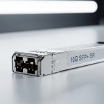
Use specific datasheet checks when matching optics. For instance, common 10GBASE-SR optics include Cisco SFP-10G-SR and Finisar FTLX8571D3BCL, while many deployments also use third-party equivalents such as FS.com SFP-10GSR-85. For Dedicated Interconnect planning, the exact model matters less than the actual optical parameters and DOM behavior, but using known-good models reduces risk during acceptance testing.
Pro Tip: In the field, “it links at first” can still be a bad optic choice. Always validate DOM-reported receive power and error counters after traffic load (for example, watch vendor-specific CRC/FEC counters and link flaps over a 30 to 60 minute soak). A transceiver that barely meets sensitivity can pass a short console test but fail under thermal drift or after connector cleaning issues compound.

Real deployment scenario: from patch panel to validated GCP circuit
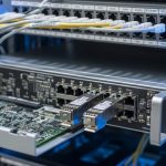
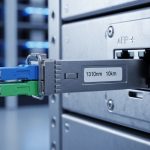
Consider a 3-tier data center leaf-spine topology where a pair of top-of-rack switches uplinks into a dedicated interconnect edge. The environment uses 10G Ethernet ports with LC duplex patching and a single-mode backbone from the meet-me-room to the edge cage. The installed fiber plant is measured during pre-acceptance: average attenuation is 0.35 dB/km at 1310 nm, with an estimated 3.0 dB total insertion including splices and patch cords. Engineers choose a 10GBASE-LR-class optic (1310 nm) with receiver sensitivity around the datasheet’s supported range and confirm the module is DOM-capable.
Operationally, the field team performs a sequence: (1) verify the transceiver form factor and wavelength family, (2) clean LC connectors using lint-free wipes and an approved solvent or dry cleaning method, (3) insert the module and confirm link up with expected negotiated speed, (4) run a traffic soak at a steady rate (for example, 8 to 9 Gbps line-rate for at least 30 minutes using a traffic generator), and (5) record DOM telemetry such as transmit power and receive power. In one common incident, the link flapped only after 20 minutes due to marginal optical margin; the fix was swapping to a long-reach module with better sensitivity headroom and re-cleaning one connector that had microscopic residue.
Decision checklist for selecting the right GCP fiber module
Use an ordered checklist so your selection is auditable and repeatable across sites. This is the same workflow engineers use when standardizing optics across multiple racks and colocation facilities.
- Distance and link budget: Use measured fiber length, splice count, connector loss, and patch cord specs to confirm the module’s reach is not just nominal. Include a margin for aging and cleaning variability.
- Wavelength family: Match the fiber type and plant characteristics (multimode for 850 nm classes; single-mode for 1310/1550 nm classes). Do not assume drawings are correct.
- Data rate and form factor: Ensure the transceiver supports the port speed (for example, SFP+ for 10G, QSFP28 for 25G/50G/100G variants). Mismatched optics can prevent link negotiation.
- Connector standard: Verify LC vs MPO/MTP and polarity requirements. For MPO, confirm polarity method (for example, A-B vs B-A) matches the patching scheme.
- DOM support and diagnostics behavior: Confirm your switch/router accepts the module’s DOM pages and that alarms are correctly interpreted. Validate with a controlled test before production cutover.
- Operating temperature and airflow: Choose modules with an appropriate temperature range for your hot aisle or enclosed rack. Field failures often correlate with high ambient and insufficient airflow.
- Switch compatibility and vendor lock-in risk: Some network OS versions enforce transceiver vendor checks or stricter threshold validation. Prefer modules validated by your switching platform documentation where possible.
- Return and RMA plan: For third-party optics, ensure you can quickly swap and document telemetry for the RMA. TCO improves when replacements are not delayed.
Common mistakes and troubleshooting for GCP fiber module issues
Even experienced teams hit recurring problems. The goal is to identify the root cause quickly, not just to “try another module.”
Link up but unstable traffic: insufficient optical margin
Root cause: Receiver sensitivity is marginal for the installed fiber attenuation plus connector and splice losses. Thermal drift can push the link below a stable operating point. Solution: Measure receive power via DOM, compare against datasheet thresholds, then swap to a module with higher sensitivity headroom or reduce insertion loss by re-cabling/cleaning.
Port stays down: wavelength or data rate mismatch
Root cause: A 850 nm SR module is installed on a single-mode path, or a long-reach module is used where the switch expects a different PHY behavior at the configured speed. Solution: Confirm the switch port configuration, module wavelength class, and that the transceiver supports the negotiated line rate and modulation format required by the PHY.
Intermittent link flaps: connector contamination or polarity error
Root cause: Microscopic contamination increases attenuation; MPO polarity mistakes can cause persistent receive failure. Solution: Clean connectors with an approved method and inspect with a microscope or inspection tool. For MPO, verify polarity against the patch panel labeling and re-terminate if necessary.
DOM-related disable: diagnostics incompatibility
Root cause: Non-compliant or partially implemented DOM telemetry causes the switch to reject the module or keep it administratively down. Solution: Check the transceiver’s DOM support details from the datasheet and validate with a known compatible vendor module. If needed, update network OS to a version that supports the module class correctly.
Cost and ROI note for optics in Dedicated Interconnect
Typical optics pricing varies by rate and reach. For example, 10GBASE-LR-class SFP+ optics often fall into a broad range depending on vendor and DOM certification, while longer-reach and higher-rate modules (25G and beyond) can cost significantly more. In TCO terms, the cheapest module is rarely the best if it increases truck rolls or extends acceptance timelines.
From an ROI perspective, OEM modules may cost more up front, but they often reduce time-to-stability because DOM thresholds and switch compatibility are well characterized. Third-party modules can be cost-effective when they are from reputable suppliers, come with complete datasheets and DOM behavior documentation, and pass your acceptance test with stable DOM telemetry and error counters under load. Plan for failure rates and spares: if you deploy multiple interconnect ports, keep at least one known-good spare per transceiver family to reduce downtime.
FAQ: choosing a GCP fiber module for Dedicated Interconnect
What fiber type should a GCP fiber module expect for Dedicated Interconnect?
Most long-reach Ethernet over fiber designs for Dedicated Interconnect use single-mode fiber with 1310 nm or 1550 nm class optics, but the exact requirement depends on your circuit design and installed plant. Confirm the service design and then validate with a measured link budget using attenuation and loss estimates from the field.
Do I need DOM support for the GCP fiber module to work reliably?
DOM is commonly required for smooth operations because network OS platforms use diagnostics for thresholds and alarms. Even when the link comes up, missing or incompatible DOM can cause admin disable, poor monitoring, or delayed fault detection. Verify DOM behavior from the transceiver datasheet and your switch compatibility guidance.
Can I use third-party optics instead of OEM modules?
Yes, but you must manage compatibility risk. Select third-party modules with complete optics and DOM specifications, and require acceptance testing that includes a traffic soak and monitoring of receive power and error counters. If your network OS enforces strict vendor checks, OEM or explicitly validated third-party optics may be necessary.
How do I confirm reach after installation?
Use measured fiber length and loss, including splice and connector losses, then compare against the module’s transmitter launch power and receiver sensitivity. If you have access to OTDR or fiber inspection tools, incorporate measured splice loss and connector inspection results to remove guesswork.
What causes link flaps even when the link initially comes up?
Common causes include marginal optical margin, thermal drift, connector contamination, and DOM threshold mismatch. The fastest path is to check DOM telemetry trends over time, then re-clean or re-seat connectors, and finally swap to a module with better sensitivity headroom if the margin is insufficient.
Where can I verify standards and transceiver behavior?
Use IEEE Ethernet specifications for PHY and link behavior context, and rely on vendor datasheets for optical parameters like wavelength, reach, power, and receiver sensitivity. For general standards references, see [Source: IEEE 802.3] [[EXT:https://standards.ieee.org/standard/]] and then confirm the module details from the specific manufacturer documentation.
If you treat a GCP fiber module selection as a measurable optics engineering task—wavelength, reach, connector, DOM, and temperature—you can avoid most Dedicated Interconnect acceptance failures. Next, review fiber link budget for data center optics to turn your measured plant data into an auditable link budget before ordering spares.
Author bio: I have deployed Ethernet over fiber in production data centers, validating optics with DOM telemetry, traffic soak tests, and connector inspection workflows. I write from the perspective of a field engineer who cares about acceptance criteria, operational telemetry, and failure-mode containment.