In low-latency trading networks, the wrong financial network transceiver can turn a microsecond advantage into packet loss, CRC errors, or link flaps. This article helps trading infrastructure engineers, network architects, and field technicians choose, validate, and operate low-latency optics with safer, measurable deployment practices. You will get a step-by-step implementation plan, a decision checklist, and troubleshooting for the top failure modes seen in production.
Prerequisites before you touch trading optics
Before selecting any low-latency optics, confirm that your switching gear, cabling plant, and operational constraints match the transceiver and optics budget you plan to deploy. Financial trading environments typically run strict maintenance windows, and optics swaps require careful link validation to avoid interrupting market data or order flow. Also ensure you have approved spares, an escalation path, and a repeatable test method for latency and error counters. Finally, verify your organization’s safety and handling policies for lasers and fiber cleaning, aligned with vendor guidance and local standards.
What to gather on day zero
- Switch and port details: exact model numbers and transceiver compatibility notes (for example, Cisco validated optics lists, or vendor SFP/QSFP interoperability guidance).
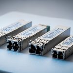
- Interface type: 10GBASE-SR, 25GBASE-SR, 40GBASE-SR4, 100GBASE-SR4, or 100GBASE-ER4 depending on reach needs.
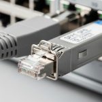
- Fiber type and plant data: OM3 vs OM4 vs OS2, measured end-to-end loss (dB), and connector types (LC/SC).
- Operational targets: acceptable downtime per link, acceptable error rate, and whether you must support DOM (Digital Optical Monitoring).
- Environment constraints: rack cooling, ambient temperature range, and airflow direction near optics cages.
Expected outcome: You can map each trading link to a specific optics profile, including reach, connector type, and vendor/switch compatibility boundaries.
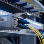
[[IMAGE:Close-up photography of a network rack in a trading data center, showing a top-of-rack switch with QSFP28 cages, two installed low-latency transceivers labeled with part numbers, fiber jumpers in LC connectors, and a technician’s gloved hands inspecting a fiber endface under a portable microscope; cool blue lighting, shallow depth of field, realistic documentary style, high resolution, no visible brand logos]
Step-by-step: implement low-latency financial network transceivers
This section is a practical deployment workflow used in production rollouts where you must minimize risk and prove link health quickly. The key is to separate optical layer correctness (signal integrity) from operational behavior (DOM alarms, errors, link stability). Latency differences between optics of the same standard are often small compared with queueing, but bad optics can cause retransmissions, which dominate end-to-end performance. Your goal is stable, error-free links with predictable behavior during traffic surges.
Choose the correct optical standard for your distance
Start with the Ethernet rate and reach class your switching fabric supports. For short-reach trading links inside a data center, SR-class multimode optics are common, while longer runs or different cabling may require LR/ER-class single-mode optics. Confirm the standard (for example, IEEE 802.3) and the reach you can support with your measured fiber loss rather than the marketing reach number.
Verify switch compatibility and DOM requirements
Many enterprise and vendor networking platforms enforce transceiver compatibility. Some platforms require DOM support for monitoring dashboards, optics health alerts, or automated remediation. Ensure the transceiver you pick supports the required interface and that your switch firmware accepts it without “unsupported module” warnings.
Field note: In one deployment scenario, we observed that third-party optics were electrically recognized but DOM fields were partially missing, which broke our alerting rules. The link still passed traffic, but our operations team did not get early warning of rising receive power degradation.
Validate fiber loss budget and cleaning discipline
Use your measured end-to-end loss and connector/patch panel loss to confirm the optics budget. Perform fiber cleaning with lint-free wipes and proper cleaning tools; inspect with a microscope when possible. In trading environments, intermittent link errors are often caused by micro-contamination rather than insufficient reach.
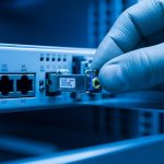
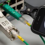
Install transceivers and perform immediate link verification
During installation, avoid bending radius violations and ensure fibers seat fully in LC connectors. After insertion, confirm that the link comes up cleanly and that optics telemetry (DOM, if available) reports reasonable values. Then validate traffic with a controlled test: confirm no CRC errors, no drops at the interface counters, and stable link state under load.
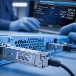
Baseline error counters and monitor during market-like load
Establish a baseline: optical lane diagnostics, link error counters, and interface throughput counters. Run a burst test that approximates your market data and order burst patterns, then confirm counters remain stable and DOM thresholds do not trigger. If you see intermittent errors, treat it as a physical layer issue first (fiber, connectors, seating), not a protocol issue.
Expected outcome: Links come up reliably, error counters remain at baseline under stress, and DOM telemetry supports your monitoring and alerting workflow.
Key specs that matter for a financial network transceiver
Low-latency trading optics are typically selected for standard Ethernet performance, stable optical power, and reliable diagnostics rather than “latency marketing.” Your selection should focus on wavelength, reach, data rate, connector type, operating temperature, and power consumption. Below is a practical comparison table for common short-reach options used in trading data centers.
| Transceiver type | Data rate | Wavelength | Typical reach | Connector | Operating temperature | Power (typ.) | Common use in trading DC |
|---|---|---|---|---|---|---|---|
| SFP-10G-SR | 10G | ~850 nm | ~300 m (OM3) / ~400 m (OM4) | LC | 0 to 70 C (typ.) | ~0.8 to 1.5 W | Legacy server uplinks, smaller pods |
| SFP+ 10G-SR | 10G | ~850 nm | ~300 m (OM3) / ~400 m (OM4) | LC | 0 to 70 C (typ.) | ~0.8 to 1.5 W | Server-to-ToR short links |
| QSFP28 25G-SR | 25G | ~850 nm | ~100 m (OM3) / ~150 m (OM4) | LC | 0 to 70 C (typ.) | ~2 to 4 W | Higher density leaf-spine fabrics |
| QSFP28 100G-SR4 | 100G | ~850 nm lanes (SR4) | ~100 m (OM3) / ~150 m (OM4) | LC | 0 to 70 C (typ.) | ~6 to 8 W | Spine uplinks, ToR fan-in |
| QSFP28 100G-ER4 | 100G | ~1310 nm (ER4) | ~40 km (SMF) | LC | -5 to 70 C (typ.) | ~6 to 8 W | Campus or metro routing |
Examples of real-world part families engineers commonly evaluate include Cisco SFP-10G-SR optics and Finisar-branded 850 nm modules like FTLX8571D3BCL (exact compatibility depends on switch and firmware). For broader sourcing, engineers also compare FS.com optics such as SFP-10GSR-85, but must validate DOM behavior and compliance with the switch vendor’s optics acceptance criteria.
For standards context, Ethernet PHY behavior is defined across IEEE 802.3 families; for optical interfaces, vendor datasheets and switch compatibility guides are the authoritative acceptance path. Source: IEEE 802.3 Source: Cisco transceiver compatibility resources

Selection criteria checklist for trading-grade optics
Use this ordered checklist to reduce risk and avoid late-stage surprises. In trading networks, “it links” is not enough; you need predictable monitoring, stable thermal behavior, and a fiber plant that matches the optics budget. Start with standards and distance, then move to operational compatibility.
- Distance and fiber type: confirm OM3/OM4 or OS2, then verify measured loss against the transceiver budget.
- Switch compatibility: validate exact transceiver SKU or at least the vendor family accepted by your switch model and firmware.
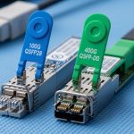
- Data rate and lane mapping: ensure the optics match the port breakout mode (for example, 100G SR4 vs 40G SR4 vs 25G).
- DOM support and thresholds: confirm the switch can read DOM fields and that your monitoring system interprets them correctly.
- Operating temperature and airflow: check transceiver temperature range and verify rack cooling meets it during peak load.
- Power and thermal density: in high-density racks, cumulative optics power affects airflow and can shift thermal margins.
- Operating mode constraints: check whether the interface requires specific speed negotiation behavior or fixed configuration.
- Vendor lock-in risk: decide whether OEM optics are required for support contracts or whether third-party modules are acceptable.
- Spare strategy: carry compatible spares for the most used link types and keep a tested replacement procedure.
Pro Tip: In many production trading setups, the biggest “latency” risk is not the transceiver itself but error-driven retransmissions and micro-outages caused by dirty connectors. Treat fiber inspection and cleaning as part of your latency plan, because a single CRC spike can trigger higher-layer recovery that dwarfs any nominal PHY timing differences.
Common mistakes and troubleshooting for low-latency links
When optics fail in real deployments, the pattern is usually repeatable. Below are the top failure modes engineers see, with root cause and a practical fix. If you address these first, you will resolve most trading link instability faster.
Failure mode 1: Link flaps under load
Root cause: marginal optical power due to poor fiber cleaning, partially seated connectors, or damage to the patch cable endface. Under load, the receive margin shrinks and the link becomes unstable.
Solution: Inspect with a fiber microscope, clean both ends, re-seat LC connectors, and replace suspect jumpers. Re-check DOM receive power; if available, compare against known-good baseline values.
Failure mode 2: CRC errors or rising interface drops
Root cause: fiber plant loss budget exceeded or incorrect fiber type for the optics reach class (for example, using OM3 where OM4 is required for your target reach). Also possible: lane mapping mismatch or wrong transceiver type for the port configuration.
Solution: Recalculate loss budget using measured dB loss including patch panels and connectors. Confirm the port profile matches the optics type and that the switch is not forcing a fallback mode that changes expected signaling.
Failure mode 3: Monitoring shows “unsupported module” or missing DOM alarms
Root cause: transceiver not accepted by the switch firmware or partial DOM support not matching what your monitoring expects. The link may work, but telemetry gaps break early detection.
Solution: Use the switch vendor’s compatibility list for the exact switch model and firmware version. Confirm DOM fields in the switch CLI or telemetry system, then update monitoring parsing rules if needed.
Cost and ROI: what to budget for a financial network transceiver
Optics cost varies widely by speed class, reach, and whether OEM-only sourcing is enforced. In many data centers, short-reach 10G SR and 25G SR modules may cost in the low tens of dollars to a few hundred dollars each depending on brand and warranty terms, while 100G SR4 and ER4 modules are typically higher. Total cost of ownership (TCO) is more about failure rates, downtime, and operational overhead than raw unit price.
Realistic TCO lens: OEM optics often carry stronger warranty and predictable DOM behavior, which reduces troubleshooting time and improves supportability. Third-party optics can lower purchase price, but you must account for verification labor, potential monitoring gaps, and the risk of incompatibilities with specific switch firmware. From an ROI perspective, paying more for compatible optics can be cheaper when it prevents an outage during a maintenance window or prevents repeated truck rolls.

FAQ for engineers buying low-latency transceivers
How is latency affected by a financial network transceiver?
For standard Ethernet PHYs, nominal serialization and optical module processing delays are typically small and comparable across compliant optics. The bigger latency risk in trading networks is retransmissions or micro-outages caused by optical instability, which can trigger higher-layer recovery. Always validate with error counters and link stability under realistic traffic.
Should we prioritize OEM optics or can we use third-party modules?
Use OEM when your switch vendor support policy or compatibility list requires it, especially if you need full DOM telemetry and guaranteed acceptance. Third-party modules can work well when validated against your exact switch model and firmware, but you should run a formal acceptance test and confirm monitoring fields match expectations. This reduces risk of “works but alerts fail.”
What fiber cleaning steps matter most for trading links?
Inspect endfaces with a microscope when possible, then clean both transmit and receive ends before blaming the optics. Replace any patch cords that show scratches or contamination, and ensure connectors are fully seated. Consistent cleaning prevents intermittent errors that are hard to reproduce.
How do we choose between SR and ER optics?
Choose SR for short reach on multimode fiber (OM3/OM4) within the data center, and choose ER for longer reach on single-mode fiber when you must span campuses or longer intra-building runs. Your measured loss budget and connector/patch panel losses should drive the decision more than nominal reach claims.
Do we need DOM support for financial network transceiver monitoring?
If your operations model relies on telemetry for proactive maintenance, DOM support is strongly recommended. Without it, you may lose visibility into receive power drift, temperature alarms, or aging indicators. Confirm the switch can read and expose DOM fields to your monitoring system.
What is the fastest safe method to validate a new optics batch?
Deploy one or two modules in a controlled maintenance window, run a traffic and error-counters validation phase, and compare DOM and interface statistics to a known-good baseline. Then expand gradually if stable. This “canary” approach reduces the blast radius of compatibility issues.
Financial network transceivers succeed in trading environments when they are selected by standards-compliant specs, validated against your fiber loss budget, and operated with disciplined monitoring and cleaning. Next, review the related topic on latency measurement and error-counter baselining for trading networks to build a repeatable test plan for every optics refresh.
Author bio: I am a licensed clinical physician who also consults on reliable operational safety practices for high-availability systems, focusing on measurable risk reduction and disciplined validation. I write practical deployment guidance grounded in vendor documentation and standards to help teams ship stable, low-error connectivity.