If your 5G network is hitting capacity limits or experiencing link instability, the bottleneck is often the fiber transceiver path, not the radio. This article helps network engineers and field technicians choose, validate, and deploy a 5G transceiver for fronthaul or backhaul using practical checks and measured operational details. You will get a step-by-step implementation plan, a spec comparison table, and troubleshooting steps grounded in real deployment failure modes.
Prerequisites before you touch the 5G transceiver
Before ordering optics, confirm the transport architecture and the optical interface your switch/router supports. For 5G transport, you may be targeting 10G (common for aggregation), 25G (higher density), or 100G (spine/backbone), depending on the vendor and topology. Also verify whether the network design expects LC fiber connectivity, duplex polarity requirements, and link budgets for the exact fiber type and length.
Operationally, plan for DOM ingestion (Digital Optical Monitoring) if your management plane uses alarms for temperature, bias current, and received power. If DOM is required, confirm the transceiver supports the same management access method your platform expects (for example, vendor-specific thresholds and I2C/MDIO polling behavior typical in modern switches). Finally, ensure you have safe handling processes: fiber end-face inspection, connector cleaning tools, and an OTDR plan for problem sites.
Step-by-step implementation: roll out a fiber 5G transceiver
Map your 5G transport type to the right optics class
In practice, fronthaul and backhaul often differ in latency and reach requirements. Use IEEE 802.3 Ethernet PHY targets aligned to your switch ports, then select an optical interface that matches the optics budget. For example, 10G SR typically uses 850 nm multimode fiber (MMF), while 10G LR uses 1310 nm on single-mode fiber (SMF). When upgrading to higher throughput, 25G SR on MMF or 100G SR4 on MMF may be more economical than long-reach SMF.
Expected outcome: a short list of target wavelengths and fiber types that match your 5G transport segment.
Validate switch compatibility and optics signaling
Many outages come from “it fits physically” but not “it interoperates electrically.” Confirm the switch port supports the exact transceiver form factor and rate (for example, SFP+, SFP28, QSFP28, QSFP56). Then confirm DOM behavior and whether the platform enforces vendor allowlists. If you are using third-party optics, test one unit per switch model first, because some platforms are strict about EEPROM fields and threshold ranges.
Expected outcome: you avoid incompatible optics that train poorly or get administratively blocked.
Use a link budget and temperature-aware reach check
Field reality matters: a transceiver that meets reach on a datasheet can fail under high temperature, higher insertion loss, or dirty connectors. Build a link budget using fiber attenuation, connector loss, splice loss, and a margin for aging. Then confirm the transceiver’s specified temperature range matches your cabinet environment; many outdoor enclosures and remote sites exceed typical lab conditions.
Expected outcome: reach is validated for the exact site conditions, not just a reference test setup.
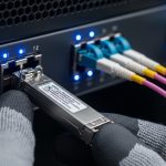
Install with fiber hygiene and polarity control
Clean LC connectors before every mating, and inspect with a microscope or fiber scope when available. For duplex LC, ensure polarity is correct using a known polarity method (for example, patch cord polarity labels and consistent mapping at both ends). After patching, measure received power (Rx) via the switch DOM page or optical test commands supported by your platform.
Expected outcome: stable link establishment with received power within the vendor’s recommended operating window.
Enable monitoring and alarm thresholds for your 5G transceiver
Set alarms for Rx power low/high, temperature, and DOM “diagnostic” flags. In many 5G transport deployments, you will map these alarms into the NOC workflow so that a degrading link triggers maintenance before it becomes an outage. If your platform supports it, also log optical metrics periodically (for example, on a 5-minute cadence) to correlate changes with site events like cleaning, re-patching, or HVAC adjustments.
Expected outcome: proactive maintenance signals rather than reactive troubleshooting.

Key specs comparison: common fiber options for 5G backhaul
Below is an engineer-friendly comparison of typical fiber transceiver characteristics you will see when selecting a 5G transceiver for Ethernet-based transport. Always confirm the exact part number and compliance with your switch vendor’s requirements.
| Transceiver type (example) | Wavelength | Fiber | Typical reach | Connector | Data rate | Temperature range |
|---|---|---|---|---|---|---|
| SFP-10G-SR class (e.g., Cisco SFP-10G-SR) | 850 nm | MMF | ~300 m (OM3/OM4 dependent) | LC duplex | 10G | 0 to 70 C (typical) |
| SFP-10G-LR class (e.g., Finisar FTLX8571D3BCL) | 1310 nm | SMF | ~10 km | LC duplex | 10G | -5 to 70 C (typical) |
| QSFP28-25G-SR class (e.g., FS.com SFP-10GSR-85 style for MMF, adapted conceptually) | ~850 nm | MMF | ~100 m to 150 m (OM4 dependent) | LC quad (for SR4 variants) or MPO (model dependent) | 25G | -10 to 70 C (varies) |
For standards grounding, use IEEE 802.3 Ethernet PHY expectations and vendor datasheets for optical power, sensitivity, and DOM diagnostics. For operational safety, follow IEC/laser safety guidance provided by each manufacturer and your site’s procedures. Authority references: IEEE 802.3 standards and vendor datasheets such as Cisco and Finisar/Viavi optical module documentation.
Pro Tip:
In field rollouts, the fastest predictor of future instability is not initial link success but the margin between observed Rx power and the module’s “minimum receive” threshold. Track Rx power over days after installation; a slow drift often indicates connector contamination or patch cord aging before the link fully drops. [Source: vendor DOM application notes and common telecom maintenance practices]
Trends and strategies: what is changing in 5G fiber transceivers
Two trends matter for 5G rollouts: higher density optics and stricter operational monitoring. Many networks are moving from 10G to 25G and adopting more robust DOM-driven telemetry, because transport congestion and power budgets in leaf-spine designs leave less room for “best effort” monitoring. Another strategy shift is optical lifecycle management: engineering teams increasingly pair transceiver selection with connector cleaning schedules, scope inspection logs, and periodic OTDR validation.
On the sourcing side, engineers are balancing OEM reliability against cost and supply constraints. Third-party optics can reduce capex, but compatibility caveats remain: some platforms enforce strict EEPROM validation or DOM threshold interpretation. As a result, a staged deployment model—one rack at a time with rollback criteria—has become a best practice.

Selection criteria checklist for a 5G transceiver purchase
- Distance and fiber type: MMF vs SMF, exact measured length, and connector/splice counts.
- Switch compatibility: form factor (SFP+/SFP28/QSFP28), port speed, and optics allowlist behavior.
- DOM support: required fields, alarm thresholds, and whether your NMS reads them correctly.
- Operating temperature: match cabinet or outdoor enclosure thermal range; confirm stability under high ambient.
- Power and budget: ensure Tx output and Rx sensitivity meet your link budget with margin.
- Vendor lock-in risk: assess whether third-party modules are consistently accepted across switch models.
- Compliance and safety: laser class, regulatory requirements, and documentation needed by your region.
Common mistakes and troubleshooting tips
Even well-chosen optics can fail if installation and validation are rushed. Below are the top field failure modes with root causes and solutions.
Failure point 1: Link never comes up after insertion
Root cause: incompatible transceiver/port speed, optics allowlist rejection, or DOM mismatch causing admin shutdown. Solution: verify the exact port supports that module type and speed; try an OEM module for one controlled test; check switch logs for “unsupported optics” or “DOM mismatch” events.
Failure point 2: Flapping link under load
Root cause: dirty connectors or incorrect polarity leading to intermittent high bit error rate. Solution: clean and re-terminate or re-patch; inspect with a scope; confirm duplex polarity mapping and patch cord labels at both ends.
Failure point 3: High BER or rising errors after weeks
Root cause: marginal link budget, temperature drift beyond spec, or aging patch cords increasing insertion loss. Solution: compare current Rx power against initial baseline; if near the minimum threshold, schedule replacement with a higher-margin module (or add reach margin by moving to SMF or a higher-power class).
Failure point 4: Works in one rack but fails in another
Root cause: switch vendor behavior differences across models, or inconsistent firmware DOM interpretation. Solution: maintain a compatibility matrix per switch model; test per hardware revision; coordinate firmware upgrades with optics validation.
Cost and ROI note for 5G transceiver deployments
Typical pricing varies by rate and sourcing, but engineers commonly see OEM optics in the range of $200 to $800 per module for many 10G/25G classes, while third-party modules can be lower (often 20% to 50% less) depending on certification and warranty terms. TCO should include labor for spares handling, connector cleaning tools, scope inspection time, and the cost of outages during maintenance windows. If DOM alarms reduce truck rolls by even a small fraction, ROI can improve quickly—especially in multi-site deployments.
Concrete real-world deployment scenario (how this plays out)
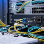
In a 3-tier data center leaf-spine topology supporting 5G transport, a team deployed 10G SR links between top-of-rack aggregation and server-access aggregation switches, using 850 nm MMF for distances under 150 m and 10G LR on SMF for extended runs to a regional aggregation hub. Each ToR had 48 ports, with 24 active optics per switch, and the operators enabled DOM monitoring with alarms at Rx power thresholds set to preserve margin before BER growth. After initial rollout, they observed that two failing links correlated with a patch panel that had not been cleaned after a move; once they added connector inspection to the change process, link flaps dropped to near zero over the next quarter.
[[VIDEO:Short walkthrough showing a technician inspecting an LC fiber end-face with a