Carrier Ethernet rollouts often stall at the “last mile” of optics: a link comes up intermittently, alarms flood dashboards, or the transceiver simply won’t train. This article helps network engineers and field technicians choose and deploy MEF fiber optic transceivers that align with Carrier Ethernet operational expectations. You will get a step-by-step implementation checklist, a practical spec comparison, and troubleshooting rooted in IEEE and vendor requirements. Update date: 2026-04-30.
Prerequisites: what to verify before you touch any fiber optic port
Before selecting optics, confirm your network uses Carrier Ethernet services and that your equipment supports the needed Ethernet PHY and management model. In real deployments, I start by documenting the switch/router part numbers, transceiver cages (for example, SFP+ vs SFP28 vs QSFP+), and the intended line rate per link. Then I validate fiber plant details: fiber type (OM3/OM4/OS2), end-to-end length, connector polish/inspection results, and whether dark fiber is already tested for attenuation and reflectance. Finally, I gather optics requirements from your target standards and your vendor’s interoperability notes.
Tools and data you should have on site
- Optical power meter and stable light source or OTDR for link loss and event mapping.
- Microscope for connector inspection (end-face scratches and dirt can mimic “bad optics”).
- Switch CLI access to confirm DOM readings, port diagnostics, and link training logs.
- Bill of materials: exact switch model, transceiver part numbers, and patch panel labeling.
Expected outcome: A verified list of candidate ports, fiber type, approximate reach, and operational constraints (temperature, budget, and maintenance window).
Step-by-step: implement MEF fiber optic links that behave predictably
Map your service profile to the correct Ethernet PHY and speed
Carrier Ethernet services commonly ride on Ethernet PHYs that your access switch or aggregation device expects. Confirm the port speed (10G, 25G, 40G, 100G) and whether the transceiver must support features like digital optical monitoring (DOM) and alarms. In practice, I have seen MEF-oriented deployments fail simply because the transceiver family was “compatible by wavelength” but not by PHY expectations (for example, wrong optics class for the cage).
Expected outcome: A confirmed port type and speed, such as 10GBASE-SR on SFP+ or 100GBASE-SR4 on QSFP28.
Choose optics based on wavelength, reach, and fiber type
MEF fiber optic selection should start with the physical reality of your fiber plant. For multimode, you typically choose 850 nm short-reach optics (SR). For single-mode, you choose 1310 nm (LR/ER depending on reach) or 1550 nm (depending on budget and dispersion assumptions). Always compare the vendor-reported reach to your measured link loss; do not rely on nominal distances alone because patch cords, adapters, and splices can dominate the budget.
Validate transceiver electrical/optical compliance and DOM behavior
Ethernet transceivers must meet the relevant standards for optical interface behavior. For example, 10GBASE-SR modules are specified in IEEE 802.3, and they use defined signaling and optical output characteristics. In field rollouts, I require DOM support consistency: if your NMS expects temperature, bias current, and received power, choose modules that expose those fields reliably and that match the vendor’s thresholds.
Expected outcome: A module choice aligned with IEEE optics behavior and your platform’s DOM expectations.
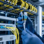
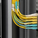
Confirm connector and polarity rules before you pull cable
Most “it should work” failures come from connector mismatch or polarity reversal. For MPO-based interfaces used in SR4 and 100G variants, verify whether your deployment uses the correct polarity method (for example, MPO polarity A vs B) and that patch cord orientation matches the transceiver mapping. For LC-based links (common in 10G SR), verify the connector end-face inspection and ensure you use the right duplex method.
Expected outcome: A confirmed connector type, polarity scheme, and inspection pass for every terminated end.
Deploy with a measured optics budget and staged verification
After install, use your light source/power meter to record baseline transmit power and receive power at the far end. Then verify link stability under typical traffic load and confirm that optical alarms do not trigger. In a real change window, I stage this: bring up a single link, confirm error counters stay flat (CRC and symbol errors), then roll to adjacent ports to catch platform-specific optics quirks.
Expected outcome: Documented baseline DOM readings and stable error counters across the first batch of links.
Pro Tip: In Carrier Ethernet deployments, many teams focus on “link up” but ignore how your platform reacts to marginal receive power. If the received optical power is near the module’s minimum sensitivity, the link can appear stable while higher-layer performance degrades under bursts. Capture DOM “rx power” and compare it against vendor minimums, not just the nominal reach.
MEF fiber optic transceiver requirements: what standards and vendors expect
Carrier Ethernet is defined around service behavior (performance, continuity, and manageability). The optics layer still must meet Ethernet PHY requirements, but MEF-aligned operations depend on predictable monitoring, alarms, and link stability. IEEE 802.3 defines optical interface behaviors for Ethernet PHYs, while vendor datasheets define operating temperature, optical power ranges, and DOM field interpretation. For operational readiness, also review your NMS integration requirements for alarms and thresholds.
Common module families you will encounter
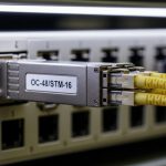
- 10GBASE-SR (850 nm, SFP+), typically used over OM3/OM4 multimode.
- 25GBASE-SR (850 nm, SFP28), frequently in access and ToR designs.
- 40G/100G SR (MPO-based variants for short reach), such as QSFP+ or QSFP28 families.

Side-by-side spec comparison for MEF fiber optic planning
Use the table below as a planning reference for common short-reach options. Always verify exact compatibility with your specific switch model and firmware, because cage wiring and DOM interpretation vary across vendors. The examples include real-world part numbers that engineers often evaluate for Carrier Ethernet lab tests and staged rollouts.
| Module example (real part) | Data rate | Wavelength | Typical reach | Connector | DOM | Operating temp (typ.) | Notes for MEF-style ops |
|---|---|---|---|---|---|---|---|
| Cisco SFP-10G-SR (example family) | 10G | 850 nm | ~300 m on OM3, ~400 m on OM4 (verify) | LC duplex | Yes (per vendor spec) | 0 to 70 C (verify datasheet) | Good for ToR-to-aggregation with OM3/OM4 |
| Finisar FTLX8571D3BCL (example 10G SR) | 10G | 850 nm | ~300 m OM3, ~400 m OM4 (verify) | LC duplex | Yes | -5 to 70 C (verify) | Often used in mixed-vendor lab validation |
| FS.com SFP-10GSR-85 (example 10G SR) | 10G | 850 nm | ~300 m OM3, ~400 m OM4 (verify) | LC duplex | Yes (check compatibility) | 0 to 70 C (verify) | Third-party cost lever; validate DOM alarms |
Expected outcome: A shortlist where wavelength, reach, connector type, DOM support, and temperature range all match your environment and your platform’s expectations.
Selection criteria checklist for MEF fiber optic in real networks
In field work, I treat transceiver selection as an engineering risk decision, not a procurement choice. The ordered checklist below is how I reduce “surprise” failures during staged rollouts.
- Distance vs measured loss: Confirm link budget using measured attenuation at install, not only spec-sheet reach.
- Switch compatibility: Verify exact switch model and port type; confirm vendor interoperability guidance.
- DOM support and thresholds: Ensure your monitoring stack reads the same DOM fields and alarm thresholds you expect.
- Operating temperature and airflow: Match module temperature range to rack thermal profile; verify with IR or sensor data.
- Fiber type and connector/polarity: Multimode OM3 vs OM4, or single-mode OS2; MPO polarity for 40G/100G SR.
- Vendor lock-in risk: Decide whether OEM-only policies are required, or whether third-party modules are acceptable with a validation plan.
- Failure management plan: Keep spares of the exact part number and revision; define RMA criteria and swap procedure.

Common mistakes and troubleshooting for MEF fiber optic links
Even when optics are “correct,” operational failures happen. Below are the top pitfalls I see most often, with root causes and fixes.
Pitfall 1: Link flaps or stays up but has rising CRC errors
Root cause: Marginal receive power due to higher-than-expected loss (dirty connectors, bad patch cords, excessive splices) or an optics speed mismatch. In Carrier Ethernet contexts, bursts can reveal the weakness.
Solution: Clean connectors, re-check end-face inspection, measure rx power at the far end, and compare against the vendor’s minimum sensitivity. Confirm the port is configured for the correct speed and that the transceiver is not forcing an unexpected mode.
Pitfall 2: Transceiver not recognized or shows “unsupported module” alarms
Root cause: Compatibility mismatch between module and switch firmware/DOM interpretation, or using an incompatible cage type. Some platforms require specific electrical characteristics or DOM behavior.
Solution: Verify the exact transceiver part number against the switch vendor’s compatibility list. Update switch firmware only within a controlled change window, then re-test with a known-good reference module.
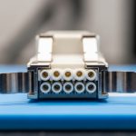
Pitfall 3: MPO polarity errors on 40G/100G SR links
Root cause: Transmit/receive lane mapping is reversed because patch cord polarity does not match the transceiver expectation.
Solution: Identify whether your system uses MPO polarity A or B, then re-terminate or swap to the correct polarity patch cord. Validate with link bring-up and confirm error counters return to baseline.
Pitfall 4: Thermal shutdown or performance degradation in hot aisles
Root cause: Module operating temperature exceeds spec because airflow is blocked or rack fans are misconfigured.
Solution: Check rack airflow direction, verify fan status, and confirm module temperatures via DOM. If needed, adjust fan curves or relocate optics to a cooler zone and retest.

Cost and ROI note: OEM vs third-party MEF fiber optic modules
Cost swings are real, but total cost of ownership is what matters. OEM modules often cost more per unit, but they can reduce troubleshooting time and compatibility risk. Third-party modules can be significantly cheaper, yet you must budget engineering time for interoperability validation, DOM/alarm matching, and potential higher failure rates depending on supply chain quality and burn-in practices.
As a planning range, many teams see OEM short-reach 10G SR modules in the “tens to low hundreds” of dollars each, while third-party equivalents may be materially lower. ROI typically comes from avoiding downtime and minimizing truck rolls; if your validation process is strong (measured power, DOM alarms, thermal checks), third-party can be cost-effective. If your environment is highly regulated or your operations demand strict vendor support, OEM-only may still be the lower-risk choice.
FAQ: MEF fiber optic transceivers for Carrier Ethernet teams
What does MEF fiber optic selection change compared with normal Ethernet optics?
MEF-aligned Carrier Ethernet operations emphasize service continuity and manageability. That means you should pay extra attention to monitoring behavior (DOM visibility, alarm thresholds), link stability under traffic bursts, and how quickly faults are detected and isolated.
Can I mix OEM and third-party MEF fiber optic transceivers in the same chassis?
Sometimes yes, but it depends on your switch model, firmware, and how the platform interprets DOM fields and alarms. Always validate with a known-good reference module and confirm that error counters and optical alarms behave correctly.
How do I verify reach for a planned MEF fiber optic link?
Use measured fiber loss and connector inspection results, then compare the margin to the module vendor’s optical budget assumptions. If possible, capture baseline transmit/receive power after install and store it in your change record.
What DOM readings should I monitor for MEF-style operational readiness?
Track temperature, transmit bias/current, transmit power, and received power. Also verify that your NMS thresholds match vendor guidance so you can detect degradation before link failures occur.
What is the most common cause of “it links but traffic is bad” in MEF fiber optic deployments?
Marginal optical power due to dirty connectors, damaged patch cords, or unexpected splice/adapter loss. Clean and re-measure; then correlate optical readings with CRC and symbol error counters during traffic bursts.
Do I need to follow specific IEEE or standards documents when choosing optics?
Yes for baseline PHY compliance; IEEE 802.3 defines the Ethernet optical interface behavior. Additionally, consult the switch vendor datasheets and interoperability guidance for practical compatibility and DOM behavior.
If you want a related planning topic, see fiber optic transceiver compatibility checks for a structured way to validate cages, DOM, and firmware behavior before cutting over services. With a measured link budget, confirmed polarity, and DOM-alarm alignment, your MEF fiber optic deployment is far more likely to stay stable under real Carrier Ethernet loads.