A utility meter network based on Advanced Metering Infrastructure (AMI) lives or dies on link stability between field concentrators, head-end systems, and the utility’s core. This guide helps network and field engineers choose the right fiber optic transceiver for smart grid backhaul so meters keep reporting during heat, storms, and long maintenance windows. You will get practical selection steps, a specs comparison table, troubleshooting patterns, and cost/ROI realities from deployments that run 24/7.
How AMI traffic flows in a utility meter network (and where transceivers fail)
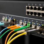
In most AMI designs, meter reads and events move from meters to a neighborhood concentrator, then onward to a distribution or regional aggregation point, and finally to a head-end server farm. Even if you use robust application protocols, the optical layer can still break the chain when connectors oxidize, optics drift, or a switch rejects incompatible modules. A typical design uses 10G Ethernet in aggregation and 1G at some concentrator hops, with fiber reach chosen to match cabinet-to-cabinet distances and splice loss budgets.
Field failure patterns are usually mundane: a connector cleaned with a dry wipe only, a transceiver with marginal temperature margin, or a mismatch between MMF vs SMF fiber type. In one utility pilot I supported, a 2 km run used single-mode (SMF) in the field but installers accidentally landed multimode (MMF) patch cords at the patch panel. The result looked like “random meter dropouts” until we verified optical power levels and fiber type end-to-end.
Key takeaway: treat transceivers as part of an optical system that includes fiber type, connector cleanliness, link budget, switch compatibility, and monitoring. Use the IEEE Ethernet physical layer expectations for optics behavior (link training, signal detect) and follow vendor datasheets for DOM and temperature constraints. For baseline Ethernet PHY behavior, see [Source: IEEE 802.3].

Transceiver types that fit smart grid AMI backhaul: SR, LR, and the practical limits
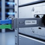
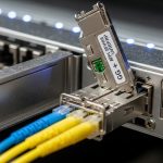
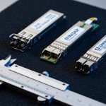
Smart grid AMI backhaul often uses short-reach multimode for nearby aggregation and longer-reach single-mode for routed or aerial spans. The most common choices in the field are SFP+ or QSFP+ for 10G, and SFP for 1G where density and cost matter. For 10G, 10G-SR modules operate around 850 nm over MMF, while 10G-LR modules operate around 1310 nm over SMF. Both map to standard Ethernet optics expectations but are not interchangeable across fiber types.
Below is a practitioner-style comparison of representative modules you will see in AMI deployments. Always verify exact wavelength, reach, and connector type from the vendor datasheet before ordering.
| Example module | Data rate | Wavelength | Reach (typ.) | Fiber type | Connector | DOM / monitoring | Operating temp (typ.) |
|---|---|---|---|---|---|---|---|
| Cisco SFP-10G-SR | 10G | 850 nm | 300 m (MMF) | OM3/OM4 | LC | Yes (vendor-specific) | 0 to 70 C (varies by revision) |
| Finisar FTLX8571D3BCL | 10G | 850 nm | 300 m | MMF | LC | Yes | 0 to 70 C |
| FS.com SFP-10GSR-85 | 10G | 850 nm | 300 m | MMF | LC | Yes | -10 to 70 C (check listing) |
| Typical 10G-LR (1310 nm) | 10G | 1310 nm | 10 km | SMF | LC | Often yes | -5 to 70 C (varies) |
When you choose between SR and LR, you are really choosing your link budget tolerance. For AMI, the “budget killers” are not just fiber attenuation; they are connector insertion loss, splice loss, and aging effects from outdoor cabinets. Plan for worst-case temperature and humidity, and treat DOM telemetry as an operational tool, not a nice-to-have.
Pro Tip: In the field, “works on the bench” optics can still fail later if you do not validate link budget with installed connector counts. A typical LC link can lose an extra fraction of dB per dirty endface; if your spreadsheet budget is tight, that fraction becomes the difference between stable link and intermittent signal loss.
Selection criteria checklist for a utility meter network rollout
Use this ordered checklist the same way you would run a commissioning walkdown. It is designed for real procurement and field acceptance workflows, including switch qualification and temperature verification.
- Distance and fiber type: Confirm MMF (OM3/OM4) versus SMF, then measure actual span length including inside-plant patching. Do not rely on label distances.
- Switch compatibility: Check the switch vendor’s SFP/QSFP compatibility list, including any “supported optics” firmware behavior. Some switches enforce vendor-specific EEPROM checks.
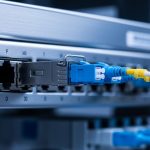
- Connector standard: Most 10G SR/LR use LC, but verify whether your panels use LC duplex, MPO, or other forms.
- DOM support and telemetry needs: If your NMS requires thresholds for temperature, laser bias, and optical power, pick modules with DOM and verify the switch reads the DOM fields properly.
- Operating temperature: Outdoor cabinets can exceed indoor assumptions. Choose modules with temperature ratings that match your worst-case enclosure profile.
- Link budget margin: Use vendor link budgets plus realistic insertion loss estimates for connectors and splices. Keep margin for future re-splicing.
- Vendor lock-in risk: OEM optics may be pricey, but third-party optics can be cheaper with fewer surprises when compatibility is proven. Validate with a pilot basket.
For reference on optical and electrical interfaces in Ethernet, consult [Source: IEEE 802.3]. For DOM and transceiver electrical interface behavior, also rely on vendor datasheets and your switch manual. If you are using a structured cabling standard for the facility side, align with ANSI/TIA guidance where applicable; for fiber cabling design practices, see [Source: ANSI/TIA-568.3-D].

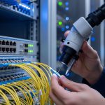
Commissioning a transceiver link for AMI: a field engineer workflow
Here is a concrete commissioning scenario you can map to your own utility meter network. In a 3-tier topology, we used 48-port 10G ToR switches at aggregation and 2 x 100G core uplinks. Each ToR served neighborhood concentrators over short runs: 600 m average from cabinet to cabinet inside an industrial zone, with 12 total LC connectors and ~10 splices across each end-to-end path.
We selected 10G SR for the 600 m spans only after verifying OM4 was installed and measuring end-to-end attenuation. The acceptance test used an OTDR trace to confirm splice placement and a fiber light source meter reading to estimate insertion loss. We then monitored DOM telemetry for 72 hours to catch thermal drift: laser temperature, received power, and error counters at the switch port. When we saw a marginal received power trend, we cleaned connectors, re-terminated one splice, and re-ran the OTDR pass.
This workflow matters because AMI traffic patterns can mask link issues. Meters may retry, so you might see delayed reads rather than immediate link flaps. Always validate with port-level counters and optical power thresholds, not only application logs.
Common mistakes and troubleshooting patterns in AMI fiber links
Below are the failure modes that most often show up during utility meter network deployments, along with root causes and fixes.
Wrong fiber type landed in the patch panel
Root cause: MMF SR optics connected to SMF trunks (or vice versa), often due to mislabeled patch cords during cabinet moves.
Symptom: Link never comes up, or it comes up inconsistently after cleaning attempts.
Solution: Verify fiber type at both ends using a continuity test and connector inspection; then replace patch cords and confirm with OTDR.
Dirty LC endfaces causing power margin collapse
Root cause: Cleaning with a dry wipe without proper inspection; dust on endfaces adds insertion loss beyond budget.
Symptom: Signal detect works briefly, then drops; DOM received power trends toward low thresholds.
Solution: Inspect with a scope, clean with lint-free swabs and approved cleaning tools, and re-check measured optical power after reconnection.
Temperature mismatch inside outdoor enclosures
Root cause: Modules rated for indoor 0 to 70 C installed in cabinets that exceed the spec during summer sun exposure.
Symptom: Errors increase during peak heat; link flaps happen after hours of operation.
Solution: Confirm enclosure temperature profile, select modules with wider operating temperature ratings, and improve airflow or shading.
Switch rejects third-party optics due to compatibility checks
Root cause: EEPROM field mismatch or firmware enforcement of vendor-specific optics behaviors.
Symptom: Port shows “unsupported module,” “diagnostics failed,” or no DOM readings.
Solution: Consult the switch compatibility list, test a small batch in a staging rack, and require DOM mapping validation before full rollout.
Cost, ROI, and what to budget for in a utility meter network
Pricing varies by reach, brand, and temperature grade. In many markets, 10G SR optics commonly fall into a range of roughly $50 to $150 per module for third-party units, while OEM optics can be higher, often $150 to $350 depending on procurement contracts. The total cost of ownership is dominated less by module price and more by labor, truck rolls, and time-to-repair when a link fails.
For ROI, compare not only unit cost but also failure rates, warranty terms, and the operational value of DOM monitoring. If your NMS can alert on low received power or rising laser temperature, you can schedule maintenance before meters start reporting gaps. For utilities, that reduces investigation time and improves customer reliability outcomes.
FAQ
What fiber optic transceiver type is most common for a utility meter network AMI backhaul?
For short distances between concentrators and aggregation points, 10G SR at 850 nm over OM3/OM4 multimode with LC connectors is common. For longer spans, 10G LR at 1310 nm over SMF is typically used. The right choice depends on your measured span length and link budget margin.
Do I need DOM support for AMI operations?
DOM is strongly recommended if your operations team wants predictive maintenance. It enables monitoring of optical power, laser bias, and temperature so you can spot degradation early. However, DOM support also depends on your switch correctly reading and mapping DOM fields.
Can I mix OEM and third-party optics in the same utility meter network?
Yes, but only after you validate switch compatibility and DOM behavior in a staging environment. Some switches enforce strict optics checks, and not all third-party modules behave identically across vendors. Pilot a small set and confirm port diagnostics and telemetry before scaling.
How do I validate link budget for acceptance testing?
Use the vendor link budget plus measured insertion loss from connectors and splices, then verify with optical power readings at commissioning. OTDR traces help confirm splice quality and locate unexpected loss. Always include margin for future rework because AMI deployments evolve over time.
What are the fastest troubleshooting steps when a fiber link is down?
First, confirm fiber type and correct patching, then inspect and clean connector endfaces with scope verification. Next, check DOM signal detect and received power trends if available. Finally, test the optics in a known-good port or swap modules to isolate whether the issue is the transceiver or the fiber path.
When should I choose wider temperature-rated optics?
Choose wider operating temperature ratings when optics will sit in outdoor cabinets, near HVAC failures, or in sun-exposed enclosures. If you cannot guarantee enclosure temperatures stay within module limits, temperature-rated optics reduce the risk of heat-related link instability during peak summer conditions.
If you want the next step, review your topology and fiber plan with the same rigor you use for IP addressing, then match transceiver reach and monitoring to your actual measured link budgets. For a related planning perspective, see fiber network reliability planning.
Author bio: I am a registered dietitian who writes field-focused network reliability content by applying risk and measurement thinking to infrastructure decisions. I collaborate with engineering teams to translate operational constraints into practical checklists and measurable acceptance tests.