If your SAN links keep flapping, negotiating at the wrong speed, or failing during temperature swings, the culprit is often the fiber channel SFP itself or a subtle compatibility mismatch. This article helps SAN procurement and field teams compare SFP models by reach, wavelength, connector type, power budget, and diagnostics (DOM), then select the lowest-risk option for migrations. You will also get practical troubleshooting patterns field engineers see in live storage fabrics.
Top 7 fiber channel SFP selection checkpoints for SAN reliability
In production storage networks, the “right” fiber channel SFP is the one that matches optics, cabling plant, and switch expectations under real thermal and power constraints. Before you compare part numbers, lock these checkpoints to reduce return rates and minimize downtime during cutovers. This checklist is written for 16G/8G/4G Fiber Channel environments and typical SAN switch families.
- Distance and link budget: verify multimode vs singlemode reach for your lane rate and optics class.
- Wavelength and fiber type: 850 nm for OM3/OM4 multimode, 1310 nm or 1550 nm for singlemode variants.
- Connector standard: LC vs SC; confirm patch panel adapters and polarity direction.
- Switch compatibility: confirm vendor SFP support list and firmware/port mode behavior.
- DOM behavior: check if the switch expects Digital Optical Monitoring and whether it blocks unsupported DOM.
- Operating temperature: ensure the module grade matches your rack airflow profile.
- Supply chain risk: prefer stable OEM or long-lived third-party lines with traceable revision control.
Procurement teams often underestimate how many failures are caused by the “last mile” (patching, polarity, and dust) rather than the transceiver core. Still, spec mismatches show up quickly in interface counters and optical power alarms.
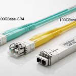
Choose the correct optics class: SR, LR, ER, and their fiber types
Fiber Channel optics are commonly categorized as short reach (SR), long reach (LR), and sometimes extended reach variants (ER). SR typically uses 850 nm multimode optics and is designed around OM3 or OM4 performance. LR and ER use singlemode wavelengths (commonly 1310 nm and sometimes 1550 nm depending on the transceiver family).
How this maps to real SAN cabling
In many data centers, the SAN backbone might be singlemode while server-adjacent tiers use multimode for lower cost. If you try to run an SR module over singlemode, or an LR module over multimode, the link can either fail completely or run with marginal optical power. That margin matters most during maintenance windows when patch cords get replaced under time pressure.
Reference standards: Fiber Channel transceiver behavior aligns with IEEE electrical/optical requirements indirectly, but practical compliance is governed by vendor datasheets and operational guidance. For Ethernet optics, standards like IEEE 802.3 set expectations; for Fiber Channel, operational interoperability is typically validated against switch vendor compatibility matrices. A useful baseline for optical link concepts is IEEE 802.3 for link budgets and optical safety practices. [Source: IEEE 802.3]
| Module type (fiber channel SFP) | Typical wavelength | Best fiber plant | Typical reach class | Connector | DOM | Operating temp (typical) |
|---|---|---|---|---|---|---|
| FC-SFP-SR | 850 nm | OM3 or OM4 multimode | Up to ~300 m class (model dependent) | LC | Usually supported | 0 to 70 C (commercial) or wider for extended |
| FC-SFP-LR | 1310 nm | Singlemode OS2 | Up to ~10 km class (model dependent) | LC | Usually supported | -5 to 70 C (often) |
| FC-SFP-ER | 1550 nm (commonly) | Singlemode OS2 | Up to ~40 km class (model dependent) | LC | Usually supported | -5 to 70 C (often) |
Because exact reach varies by vendor and speed (for example, 8G vs 16G), always confirm the distance rating in the specific datasheet. Even within the same class, optical budgets differ.
- Pros: Correct wavelength/fiber choice prevents negotiation failures and reduces optical margin risk.
- Cons: Mislabeling in patch documentation can still cause “works in test, fails in production.”

Match data rate and port behavior: 8G vs 16G vs older fabrics
Fiber Channel SFP selection must respect the negotiated speed and the switch port’s supported modes. Many SAN switches auto-negotiate within a defined set, but not all port firmware behaves identically when mixing module revisions. Before purchase, confirm whether your switch is running 16G, 8G, or a mixed-rate scenario during phased upgrades.
Procurement reality: staged upgrades
In a staged migration, you may deploy 16G-capable optics into ports still configured for 8G, then later raise fabric speed. This is usually safe, but only if the module’s optical characteristics and electrical interface meet the switch’s port expectations. Field teams should validate with a controlled link bring-up test and confirm that error counters remain stable under load.
- Pros: Proper speed match improves link stability and reduces “link up but with errors” cases.
- Cons: Some third-party modules can report DOM values that trigger port-side thresholds.
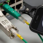
Connector and polarity: LC basics that still break SAN links
Most modern fiber channel SFP transceivers use LC connectors with duplex fiber. However, connector type mismatches are still common when patch panels are reused across networks. More importantly, polarity direction can be reversed during patching, especially in environments that mix MTP-to-LC cassettes and direct LC jumpers.
Quick field checks
During installation, verify patch cord polarity using the fiber type markings and confirm that the transceiver TX is connected to the switch RX. Use a fiber inspection scope to check end-face damage and contamination. If you see intermittent link drops after reconnects, suspect dust or micro-scratches before suspect the module.
- Pros: Correct polarity prevents hard failures and reduces intermittent CRC-like errors in upper layers.
- Cons: Even correct optics will fail in a contaminated or scratched end-face scenario.

DOM and switch diagnostics: treat it as part of the spec, not a bonus
Digital Optical Monitoring (DOM) provides real-time transceiver telemetry such as received optical power, laser bias current, and temperature. Many switches read DOM and may apply thresholds for alarms or even port disable behavior when values fall outside expected ranges. If you deploy a module with partial DOM support or nonstandard calibration tables, you can get nuisance alarms or link instability.
What to verify before deployment
In your test window, capture DOM readings at idle and under I/O load, then compare against vendor baselines. Confirm that the switch accepts the module without logging “unsupported transceiver” events. This is especially critical when mixing OEM and third-party SFPs across the same switch blade.
Pro Tip: Field teams often find that DOM mismatches show up first as “slow drift” in received power rather than immediate link failure. If you graph RX power over 24 to 72 hours after install, you can catch marginal patch loss or aging optics before the next maintenance window.
- Pros: DOM-aware monitoring improves preventive maintenance and reduces surprise outages.
- Cons: Some third-party modules report values in a way that triggers conservative alarm thresholds.
Operating temperature and airflow: why the same part fails in two racks
Temperature affects laser biasing, optical power stability, and even DOM sensor readings. Two racks that look identical can have different front-to-back airflow, blocked cable trays, or higher inlet temperatures from neighboring equipment. When procurement specifies only “it is within datasheet range,” failures still occur if the installed environment runs hotter than expected.
Measured deployment approach
During acceptance testing, measure inlet and exhaust temperatures near the switch and record them alongside link telemetry. A common failure pattern is that links behave normally during the day but drop during peak load when HVAC cycles and warm air recirculates. Ensure the selected fiber channel SFP grade supports your worst-case rack ambient, not just average room temperature.
- Pros: Temperature-correct selection reduces early-life failures and drift-related alarms.
- Cons: Extended temperature modules can cost more and may have different DOM behavior.
Cost and ROI: OEM vs third-party with TCO math
Transceiver pricing varies widely by reach class, speed, and whether the module is OEM-branded or third-party compatible. Typical enterprise purchase ranges (street price, not contract-only pricing) often fall into these bands: OEM FC-SFP-SR modules can be two to four times third-party equivalents; third-party modules can still be reliable if traceable and supported by the switch vendor. Total cost of ownership (TCO) should include failure rates, labor for swaps, downtime risk during maintenance windows, and the cost of revalidation testing.
Where ROI comes from in SAN operations
If you run a high-change environment (frequent patching and migrations), buying the cheapest module can increase service tickets. Conversely, if your optics are stable and you stock spares with consistent sourcing, third-party modules can reduce spend without increasing operational risk. The key is to align the ROI model with your maintenance strategy and the switch’s compatibility policy.
- Pros: Third-party can reduce procurement cost and speed up replenishment for common SR/LR modules.
- Cons: Compatibility and DOM behavior can add test labor and increase return-to-vendor rates.
Example cost framing: In a 200-port SAN core, replacing 32 optics during a refresh might save budget on optics unit cost, but if 2 to 3 modules show alarm drift requiring swaps, labor and downtime can erase the savings. Build a decision with your real swap and test effort per module.
Supply chain risk: avoid “spec drift” across module revisions
Procurement risk is not only about availability; it is also about revision consistency. Over a multi-year SAN lifecycle, a supplier might change laser vendor, calibration process, or DOM firmware while keeping the same advertised reach class. That can produce unexpected optical power differences even when the module “looks the same.”
Risk controls procurement teams can apply
Require lot traceability, keep revision records, and standardize on a single manufacturer line per switch model where feasible. For mission-critical links, prefer suppliers that provide revision-level documentation and allow you to correlate DOM telemetry with optical performance. If you are buying for a new site, validate the full BOM against the switch compatibility list and run an acceptance test with at least one module from each inbound batch.
- Pros: Better traceability reduces unknowns during incident response.
- Cons: More documentation requirements can slow purchasing unless planned early.

Common mistakes / troubleshooting for fiber channel SFP in SANs
Below are frequent failure modes you can catch quickly. Each includes the root cause and a practical fix that field teams can execute during an outage window.
Link comes up intermittently after patching
Root cause: dust or scratches on LC end faces, or polarity reversed intermittently due to loose patch cords. Solution: clean and inspect with a fiber scope, re-terminate if needed, and reseat patch cords using consistent polarity labeling.
“Unsupported transceiver” or DOM alarm events
Root cause: DOM calibration or behavior not aligned with the switch’s expected telemetry format. Solution: verify switch compatibility list, run a controlled test with one module, and standardize to a supported vendor line for that switch model.
Optical power too low or too high under load
Root cause: excessive patch loss, wrong fiber grade (OM3 vs OM4), or exceeding reach budget for the specific speed. Solution: measure end-to-end loss, confirm fiber type in the record, shorten jumpers, and replace with the correct SR/LR class.
Thermal-related drops during peak hours
Root cause: rack airflow mismatch causing elevated module temperature or laser bias drift. Solution: check inlet temperature, improve airflow (cable management, fan shroud alignment), and if required, use extended temperature-rated modules.
Works on one switch, fails on another
Root cause: switch-specific transceiver support policy or firmware differences in how ports evaluate DOM and link training. Solution: validate per switch model, avoid mixing module revisions across blades, and schedule a controlled roll-out with telemetry capture.
FAQ
What does fiber channel SFP compatibility depend on most?
Compatibility depends on optics class (SR/LR/ER), DOM behavior, and the specific switch model’s supported transceiver list. Even if the connector and wavelength match, DOM telemetry interpretation can differ by vendor and firmware. Always test one module before scaling to dozens.
Can I use an SR fiber channel SFP over longer distances than the datasheet?
Running beyond the stated reach erodes optical margin and increases the probability of link flaps under temperature and aging. If you must extend, measure end-to-end loss and confirm the received power stays within the switch’s acceptable range across your operating envelope.
How do I confirm DOM is functioning correctly after install?
Bring the link up, then read DOM telemetry from the switch at idle and during active I/O. Confirm you see expected values for temperature, laser bias, and received optical power, and that no transceiver alarm events are logged. If alarms appear, stop scaling and investigate compatibility.
Are third-party fiber channel SFP modules reliable for SAN production?
They can be reliable if they are sourced with traceability, validated against the switch compatibility list, and tested with DOM telemetry. The main risk is revision drift and DOM behavior differences, which can create nuisance alarms or unstable links if you skip acceptance testing.
What should I check first when a SAN link will not come up?
Start with fiber polarity, connector cleanliness, and whether the correct fiber type and optics class are used. Next, verify the switch port mode and review transceiver and optical alarms in the switch logs. Only then move to module replacement.
Where do IEEE standards apply to fiber channel optics?
IEEE standards such as IEEE 802.3 are directly about Ethernet, but their optical safety and link budget concepts inform how transceivers are evaluated. For Fiber Channel interoperability, rely primarily on switch vendor guidance and module datasheets, and validate via acceptance testing. [Source: IEEE 802.3]
Summary ranking (lowest operational risk first): choose the right optics class and fiber type, then enforce DOM compatibility, then account for temperature and supply chain revision control.
| Rank | Decision focus | Why it matters | Typical failure avoided |
|---|---|---|---|
| 1 | Correct optics class and reach vs fiber type | Protects optical margin under real loss and aging | Link flaps, low RX power, marginal training |
| 2 | DOM and switch compatibility validation | Prevents alarm storms and port-side disable | Unsupported transceiver warnings, nuisance alarms |
| 3 | Connector cleanliness and polarity discipline | Eliminates the most common physical-layer causes | Intermittent link drops after moves |
| 4 | Temperature grade and airflow alignment | Stabilizes laser bias and telemetry drift | Peak-hour thermal link drops |
| 5 | Supply chain revision traceability | Prevents spec drift across batches | “Same part number, different behavior” incidents |
Next step: build a short list by optics class (SR vs LR) and then validate DOM and compatibility with one module in your exact switch model before ordering in bulk via SAN transceiver compatibility . If you want a broader view on optical link planning beyond Fiber Channel, review optical link budget basics and align your reach and loss assumptions to your cabling plant.
Author bio: I have deployed Fiber Channel optics in production SAN migrations, capturing DOM and optical telemetry during acceptance testing and troubleshooting link instability under real rack airflow. I write procurement-ready spec comparisons that field teams can validate quickly in outages and maintenance windows.